3 connection and display elements, Connection and display elements – Festo Электрический терминал СРХ User Manual
Page 38
2. Installation
2−6
Festo P.BE−CPX−CEC−EN en 1004a
2.3
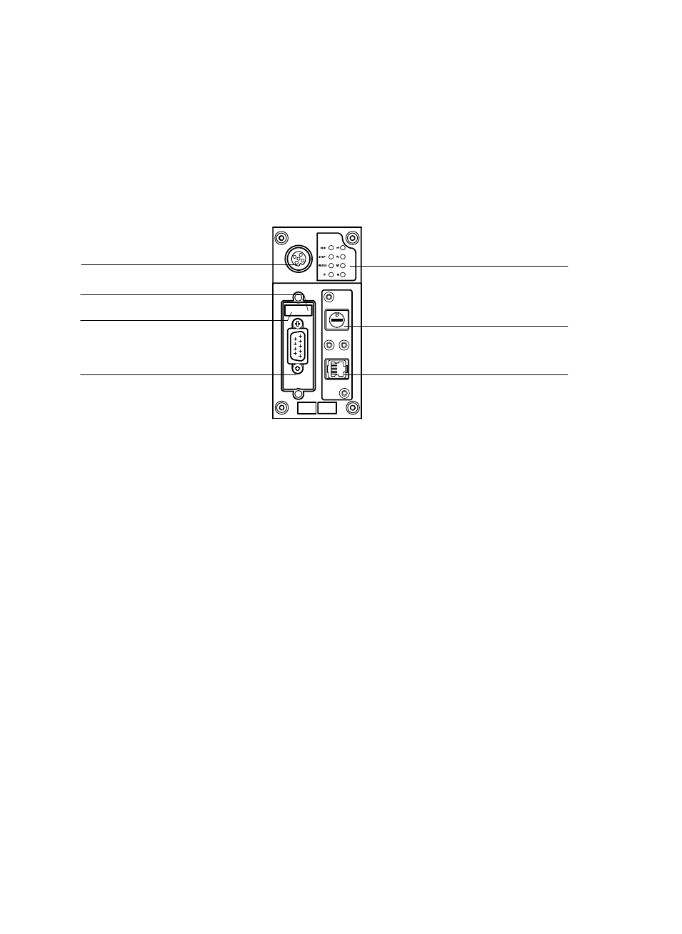
Connection and display elements
2
3
4
6
7
5
1
1
Status LEDs
2
RUN/STOP rotary switch
3
Ethernet interface
(10/100BaseT, RJ45)
4
CPX−CEC−C1/−M1:
CANopen interface
(plug, 9−pin, Sub−D )
CPX−CEC:
RS232 interface
(socket, 9−pin, Sub−D)
5
DIL switch 1
6
DIL switch 2
7
Connection for a handheld of type
CPX−MMI
Fig. 2/2:
Connection and display elements (here for CPX−CEC−C1/−M1 as an example)
This manual is related to the following products: