Festo Контроллер крайних положений SPC11 User Manual
Page 29
1. Summary of components
1-17
Festo P.BE-SPC11-DGP-EN en 0012NH
1
2
1
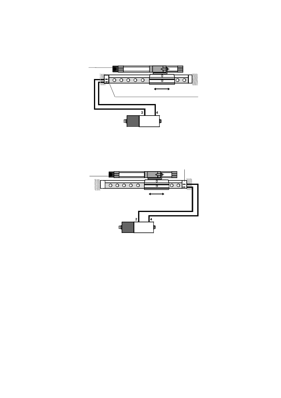
Electrical connection (measuring system zero point)
2
Arrows mark the direction of movement
Fig. 1/6: Tubing on the side opposite that with the measur-
ing system zero point
1
2
1
Electrical connection (measuring system zero point)
2
Arrows mark the direction of movement
Fig. 1/7: Tubing on the side opposite that with the measur-
ing system zero point