RMS Technologies R256 CONTROLLER/DRIVER User Manual
Page 26
Take a look at position #7. If we were to draw the arrow
at position 7 as the hypotenuse of a triangle, it would
look like the triangle to our left. Recall from geometry a
90°-45°-45° triangle is a 1-1-√2 combination. The √2,
or 1.4 value is also the radius of the dotted circle shown
above. Therefore, during certain steps, Phases A or B will
receive 1.4 Amps of current. But the average, or RMS
current throughout these 8 steps is only 1.0 Amps. RMS
and Amps/Phase is the same meaning.
The 1.4A along this hypotenuse is also known as the 2-Phase On position, since both A and
B Phases are “On” and receive current. It is also known as the peak current.
As we see the waveform that’s plotted for the A Phase, the highest value on the curve is
known as the peak value.
Motors have a rated current, or average RMS value since in operation, the current is
continuously changing. The most logical way to describe a rating is to take an average, or
RMS (root means squared) value. But drivers understand current in terms of peak current,
therefore the conversion is: Amps/Phase x 1.4 = Amps Peak
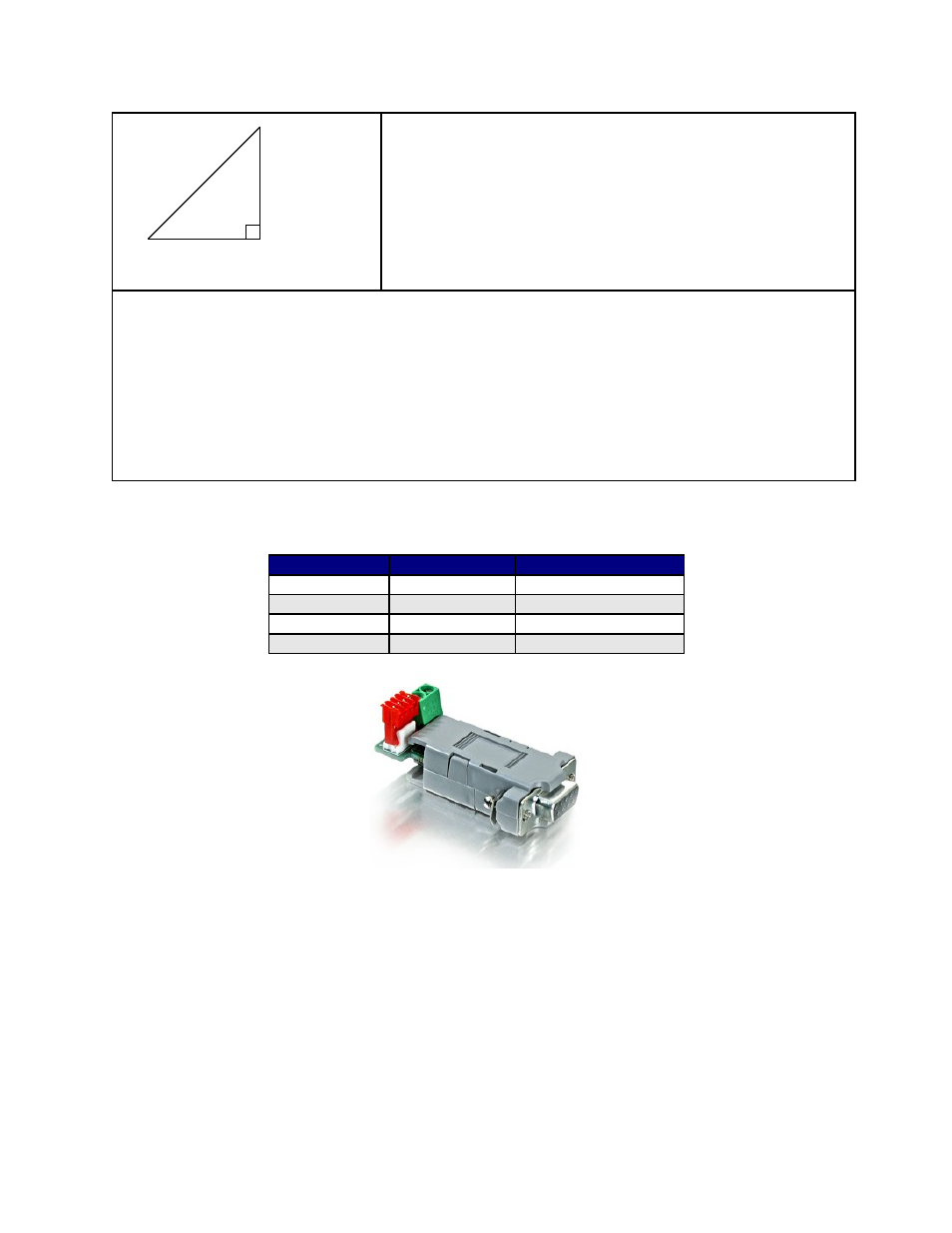
Connecting to the RS232 card (old non-RoHS version)
R256 pin#
R256 color
RS232 card pin#
4
Black/white
A (RS485A)
3
Brown
B (RS485B)
6
Green
- (GND)
1
Red
+ (PWR)
The RS232 card requires power (7-40VDC). Power is then sent to the motor via the Red 4-Pin connector.
RMS Technologies
Page 26
Version 1.05
R256 Controller Manual
4/3/2009
1.41 AMP
1 AMP
1 AMP
(√2)