RMS Technologies R256 CONTROLLER/DRIVER User Manual
Page 20
Encoder Usage
The R256 can also be used as reference to home by connecting to an US Digital E2
Encoder. The pinouts are as follows:
Pin Number Function
1
Ground
2
Index
3
Channel A
4
+ 5 VDC
5
Channel B
Table 9
The E2 encoder requires a separate +5 Volt power supply, as the R256 controller
cannot provide a strong enough source of power.
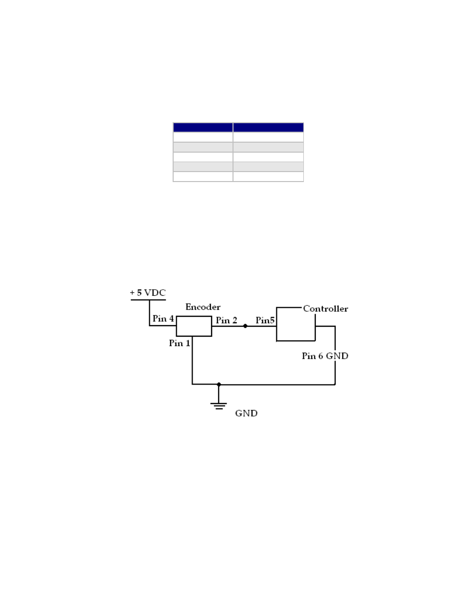
In order to use the Indexer as a reference to home, connect Pin 2 from the encoder
to one of the inputs on the controller. From the controller’s side, for best results use
Pin 5, the switch closure to ground.
In addition, use a pull-down resistor (10k Ω) to ensure that the controller will
recognize the difference between high and low (4.85V and 0.5V).
Figure 17: Encoder Pin Connection Schematic
After successfully connecting the encoder to the controller, now you can program the
controller to run continuously. The motor will stop movement when the indexer goes
high. This will send the high signal to Pin 5 on the controller.
If using channel 1, use this command to start the homing routine:
/1P0R
RMS Technologies
Page 20
Version 1.05
R256 Controller Manual
4/3/2009