Bell & Gossett VTP2006 Series VTP – Vertical Turbine Pumps User Manual
Page 18
18
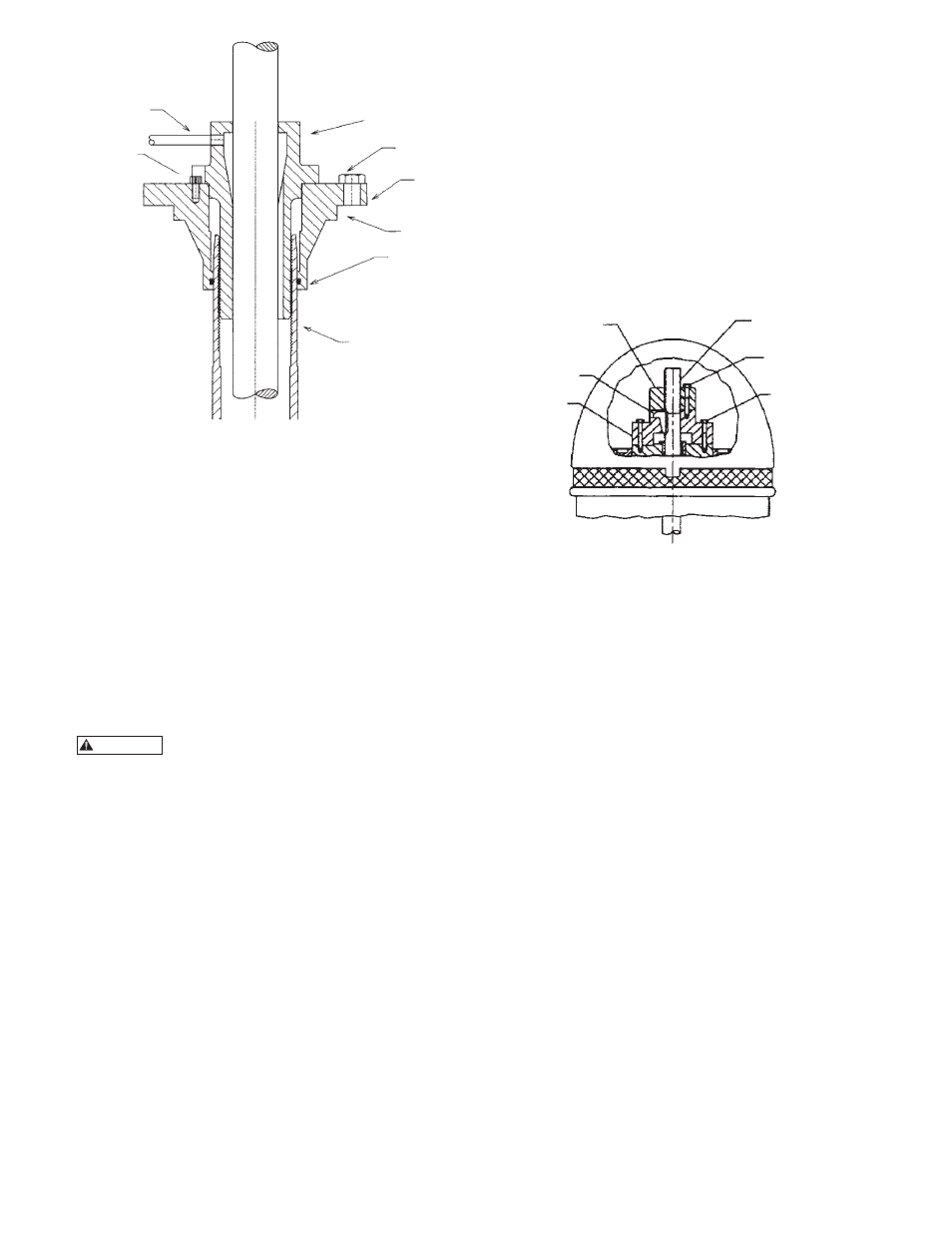
Figure 11
4. Clean the tension nut (623) and lightly oil its bore
and the threads. Screw the tension nut into the tube
nipple until the flange face of the nut contact the
tension plate.
5. For setting less than 100 feet, tighten the tension nut
until a slot aligns with the nearest locking position.
Install the locking bolt.
INSTALLING THE DRIVER
INSTALLATION OF A HOLLOW SHAFT DRIVER
This refers to either VHS type electric motors or hollow
shaft type gear drives. A small paragraph will be devoted
to combination electric motor and right angle gear
drives.
Do not work under a heavy suspended
object unless there is a positive support
and safe guards which will protect personnel should a
hoist or sling fail.
1. The driving mechanism of all hollow shaft driver is
shown on Figure 12. The head shaft (608) extends
up through the quill or hollow shaft of the driver
and is held in place by an adjusting nut (604), which
not only carries all the static and hydraulic thrust
of the impellers and shaft, but also provides the
adjustment for the impeller clearances. The head
shaft is connected to top shaft (or stub shaft) by a
threaded coupling or a rigid flange coupling.
2. When a motor stand is furnished and not installed,
proceed as follows:
A. Hoist the motor stand, inspect the mounting
surfaces, register and clean these surfaces
thoroughly.
B. Install the motor stand on discharge head and
secure with capscrews provided.
3. Attach a sling to the lifting lugs of driver and hoist
the driver up. Inspect the mounting surface, register
and clean these surfaces thoroughly. If any burrs
are found, remove burrs with a smooth mill file,
cleaning thoroughly afterward.
4. For motor, orient the motor conduit box in the
required position. For the right angle gear, orient
the input shaft to the desire position. Align the
driver mounting holes with the mating tapped holes
on the discharge head. Lower the driver until the
registers engage and the driver rests on the discharge
head. Secure driver with capscrews provided.
5. Lubricate the driver bearings in accordance with
instructions given on lubrication plate attached to
the driver case (or in the motor IOM).
Figure 12
6. After lowering and orienting the driver as explained
above, remove the drive coupling and the hold
down bolts (See Figure 12). Be sure to mark the
location of the coupling before removing it.
7. Lower the head shaft through the motor quill shaft
to meet the shaft coupling. Apply a thin film of oil
to head shaft threads (if non-galling material) and
screw into the shaft coupling (located above the
stuffing box). Make sure the shaft is not damaged in
any way. Tighten the joint.
8. Check that the head shaft centers inside the driver
quill shaft within 0.06” (1.5 mm). If it does not,
misalignment is indicated.
9. Any head shaft misalignment with driver quill
shaft could be caused by a bent headshaft, burrs,
or foreign matter between shaft ends or any of the
mounting flanges: motor flange to discharge head
top flange, discharge head base flange to base plate
or the base plate itself could be out of level. If the
latter, shim between base plate and discharge head
base, will correct it. Also, check concentricity of
motor to motor-stand (if provided) to discharge
head.
10. With the motor in place and the head shaft
projecting through the motor quill shaft, make
temporary electrical connection to check the motor
rotation. (Be sure to remove the ratchet pins or balls
before checking motor rotation.) Motor must rotate
counter-clockwise when viewed from the top. See
arrow on pump name plate. If motor does not rotate
counter-clockwise, you can change the rotation by
HEADSHAFT (608)
CAPSCREW (760)
ADJUSTING NUT
HOLD
DOWN BOLT
(604)
ADJUSTING NUT
(730) GIB KEY
DRIVE
COUPLING
LUBE LINE
(635)
LOCK BOLT
(636)
TENSION NUT
(623)
CAPSCREWS
TENSION PLATE
(625)
GASKET
(779)
O-RING
(620)
TUBE NIPPLE
(629)
WARNING