Assembly, Warning, Right side view) – Rivera Primo Powerdrive 6 Transmission Shifter Cam & Fork Assembly User Manual
Page 3
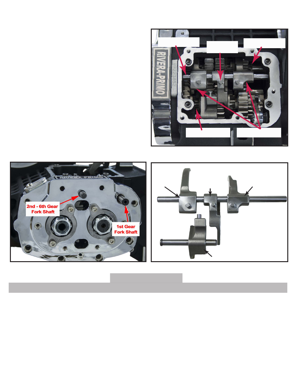
Shifter Shaft
Centered
Pin
Main Shaft
Counter Shaft
Offset Outboard
Left Side
4th & 6th Gear
Shifter Fork
2nd Gear
Shifter Fork
3rd & 5th Gear
Shifter Fork
Right Side
1st Gear
Shifter Fork
Shifter Fork Identification
Shifter Forks
Remove Fork Shaft/Shifter Forks
(Right Side View)
Fig.5
Fig.7
Fig.6
Fig.2
Assembly
1. Find the shifter fork with the centered pin. Holding
the fork so that the pin is positioned at the rear of
the transmission case, install the fork in the counter-
shaft gear fork groove. (See Fig. 6)
2. Slide the two outer forks into mainshaft gear fork
grooves so that pins are positioned on the inside
(See Fig. 6)
3. Insert the fork shaft into the hole on the right side
of the transmission case. Slide the shaft through the
shifter forks and into the hole on the
left side of the case.
4. Place 1st gear shifter fork in groove on the trap door
side of the countershaft.
5. Insert the short fork shaft with the shoulder in last
into the forward hole on the right side of the trans-
mission case. Hand thread the plug and then tighten
until it bottoms with a 1/4” hex key.
6. Check the sliding movement of the forks and gears.
All parts must move freely without binding.
a. Place Left support block under ram of arbor press. Center
new roller bearing over bore with the lettered side up. Us-
ing a suitable driver, press against outer race until bearing
makes firm contact with the counter bore. (See Fig. 9)
b. Slide left support block onto end of shifter cam then
secure with a new retaining ring.
c. Center a new roller bearing over right support block with
the lettered side up. Using a suitable driver, press against
outer race until bearing makes firm contact with the
counterbore. (See Fig. 10)
d. Raising the detent arm up, slide right support block onto
opposite end of shifter cam.
e. To replace the detent spring or detent arm assy., carefully
remove the spring by lifting up on the looped end from
the detent arm with a flat blade screwdriver and sliding
it off the spring hanger. If necessary, drive the hollow roll
pin out of the right support block and remove the spring
hanger and detent arm to replace the detent arm assy.
(See Fig. 11)
WARNING
Always wear proper eye protection when removing retaining rings.
7. If disassembled, assemble shifter cam assembly as follows: