Installation – Australian Monitor IN600 User Manual
Page 6
PAGE 6
IN600 INSTALLATION AND OPERATION MANUAL
INSTALLATION
POWER CONNECTION
Ensure the mains voltage supply matches the rear of the IN600 (+/- 10%).
Ensure that all system grounds (earth) are connected to a common point. Avoid
powering equipment within a system from multiple power sources that may be
separated by large distances. This will eliminate ground loops that are heard
as 50/60Hz humming or buzzing in speakers and seen as moving or stationary
bars on video equipment.
OUTPUT CONNECTION
Video
Video outputs are on either unbalanced RCA sockets (composite) or 15 pin high
density female connectors D-connectors (VGA). The maximum cable length for
composite video is typically less than 3m for shielded wire and 10m for coaxial
before signal degradation. This will depend on the cable quality.
There are two composite outputs for running to 2 different monitors without the
need for an external distribution amplifi er.
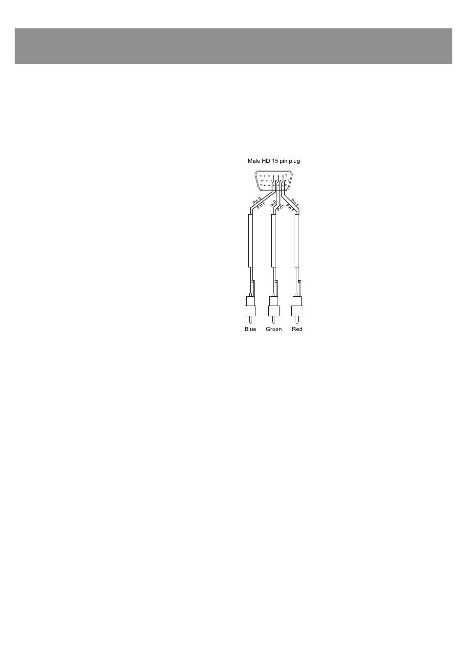
VGA pin out
1 Red
out
2 Green
out
3 Blue
out
4
Monitor ID 2 in
5 Ground
6 Red
return
7 Green
return
8 Blue
return
9 no
pin
10 Sync
return
11 Monitor ID 0 in
12 Monitor ID 1 in
13 Horizonal Sync out
14 Vertical Sync out
15 reserved (monitor ID 3)
Only pins 1,2,3,5,6,7,8,10,13,14 are used in the IN600.
BREAK OUT CABLE
INPUT CONNECTIONS
Audio
All the inputs are unbalanced RCA sockets. Unbalanced RCA wiring should be
keep as short as possible. Typically less than 3m.
Video
Video inputs are on either unbalanced RCA sockets (composite) or 15 pin high
density female connectors D-connectors (VGA). The maximum cable length for
composite video is typically less than 3m for shielded wire and 10m for coaxial
before signal degradation. This will depend on the cable quality.
RS485 CONNECTIONS
The RS485 data port is on a 5.08mm pluggable connectors. Twisted pair
cabling should be used When connecting RS485 devices, such as CAT3, CAT5,
CAT5e or CAT6 UTP cabling. RS485 data networks should be wired in a ‘daisy
chain’ confi guration with a maximum of 32 devices in the chain. The IN400 is
not terminated so may be inserted anywhere in the data network. If the IN600 is
being used at the end of a chain, a 120ohm (characteristic impedance of UTP)
terminating resistor should be connected between the + and - connections.
The maximum length of the chain is 1200m (4000’).
All installation work should be done with the power disconnected. The following information will help with installation. After installation is complete power up in the
following order:
1. All the sources
2. IN600
3. All amplifi ers
Component video can be used on the IN600
by using a VGA break out cable. A break out
cable is required for all devices. There is no
internal VGA to component conversion within
the IN600. (ie. the lines are simply switched and
the component signals require sync on them, eg
sync on green). You can not use a VGA source in
to a component source out for example.