Goulds Pumps 3796 i-FRAME - IOM User Manual
Page 92
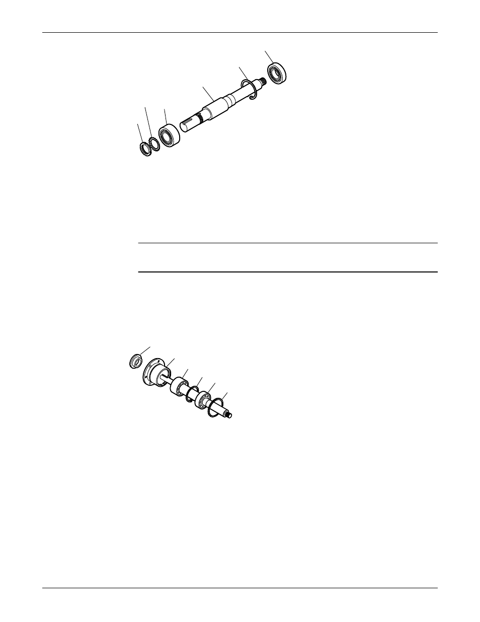
168
361A
122
112
382
136
9. Prepare the shaft for assembly as follows (see the illustration):
a) Install a new O-ring (496).
b) Coat the outside of the outboard bearing (112A) with oil.
c) Coat the bore of the bearing housing (134) with oil.
d) Put the bearing housing (134) onto the shaft.
Do not use force.
e) Insert the bearing-retaining ring (361A) into the bore groove of the bearing housing (134).
NOTICE: Ensure that the space between the ends of the retaining ring are located in the oil-
return groove. Failure to do so may result in oil-flow obstruction.
Make sure that the shaft rotates freely.
f) Install the outboard labyrinth oil-seal (332A) into the bearing housing (134).
Place the drain slots of the oil seal at the bottom position (6 o’clock).
Make sure that the edges of the keyway are free from burrs. To protect the O-ring, cover the
keyway lengthwise with a piece of electrical tape before you install the oil seal.
332A
134
112
361A
168A
496
10. Install the shaft assembly into the bearing frame as follows (see the illustration):
a) Coat the outside of the bearing housing (134) with oil.
b) Coat all the internal surfaces of the bearing frame (228) with oil.
c) Install the shaft assembly into the bearing frame (228).
Make sure that the shaft rotates freely.
d) Install the clamp bolts (370C) in the bearing housing (134) and tighten by hand.
e) Install the jack bolts (370D) with the locknuts (423) in the bearing housing (134) and tighten by
hand.
Maintenance (Continued)
90
Model 3796 i-FRAME Installation, Operation, and Maintenance Manual