Seal-chamber cover removal – Goulds Pumps 3796 i-FRAME - IOM User Manual
Page 75
4. Repeat step 3 until the impeller becomes loose.
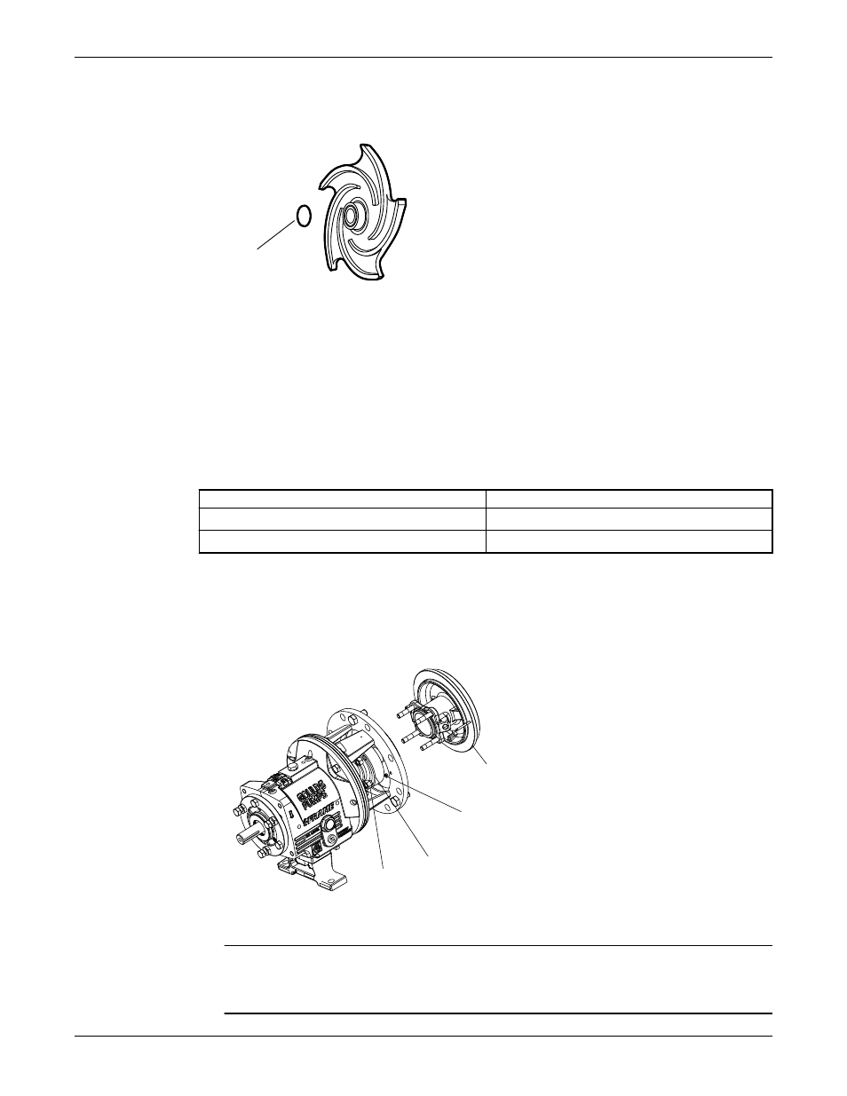
5. Remove and discard the impeller O-ring (412A).
You will insert a new O-ring during reassembly.
412A
Figure 17: O-ring for models 3196, HT 3196, NM 3196, 3198, and 3796
If the impeller cannot be removed by the previous methods, cut the shaft between the gland and the
frame, remove the impeller, stuffing-box cover, gland, sleeve, and shaft end as a unit. Do not apply heat.
Seal-chamber cover removal
Seal-chamber removal procedures
Choose from one of these procedures to remove the seal-chamber cover.
Table 9: Procedures for seal-chamber cover removal by model
Model
Procedure
3196, CV 3196, HT 3196, LF 3196, 3796
Remove the seal-chamber cover.
NM 3196, 3198
Remove the seal-chamber cover and/or backplate.
Remove the seal-chamber cover (3196, CV 3196, HT 3196, LF 3196, 3796)
1. Remove the gland stud nuts (355).
2. Remove the seal-chamber stud nuts (370H).
3. Remove the seal chamber (184).
184
355
250
370H
4. Remove the shaft sleeve (126) if it is used.
The mechanical seal is attached to the sleeve.
NOTICE: Be careful with the stationary portion of the mechanical seal that is either clamped
between the backplate and the gland or seated in the seal-chamber bore. Failure to do so may result in
equipment damage.
Maintenance (Continued)
Model 3796 i-FRAME Installation, Operation, and Maintenance Manual
73