Goulds Pumps 3620 - IOM User Manual
Page 65
Maintenance
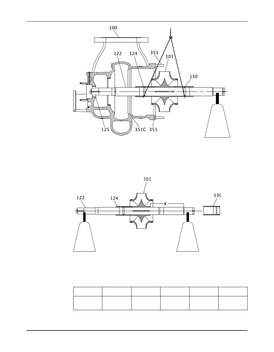
8. Reposition the slings around the impeller (101) on the locknuts (124 and 130).
9. Pull the rotor out of the pump.
10. Remove the casing gaskets(351 and 351C). (351 and 351C).
11. Remove the radial end impeller locknut (124).
You do not need to remove the thrust locknut (130) from the shaft unless you plan to
replace either the thrust locknut or the shaft.
12. Measure and record the X dimension where indicated in the figure.
This value is required for the correct positioning of the impeller in the casing at reassembly.
The X dimension is pre-set at the factory. Refer to the Impeller setting table.
Table 1: Impeller setting
This table shows the factory settings for positioning the impeller. The X dimension is given in inches
(millimeters).
Frame group
Nameplate
Size
Ball/ball
Sleeve/ball
KTB
radial bearing
arrangement
arrangement
arrangement
13.48 (342)
S
6309
All
Includes spacer
217
Model 3620, API Type BB2 Single Stage / ISO 13709 1st/2nd Ed. / API 610 8th-11th Ed. Installation, Operation, and
63
Maintenance Manual