Coupling guard assembly – Goulds Pumps 3620 - IOM User Manual
Page 35
Commissioning, Startup, Operation, and Shutdown
1. Check the gap between the coupling hubs against the dimensions shown on the elevation
drawing or as stamped on the coupling hub. For any necessary adjustment, move the
driver not the pump.
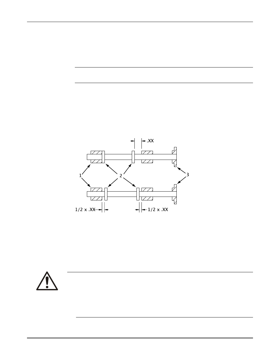
Motors with sleeve bearings may be manufactured with 1/4 or 1/2 in. (6.35 or 12.7 mm) end
movement (float) in the motor rotor. For limited end-float arrangement, the gap between the
coupling halves must be set in a different manner. If specific directions are not indicated in
the motor instructions, then follow this procedure:
NOTICE:
If the driver was mounted at the factory, the setting for the coupling is already determined.
a) Slide the rotor towards the outboard end of the motor as far as it will go and mark the
shaft at the motor frame.
b) Slide the rotor towards the inboard end of the motor as far as it will go and mark the
shaft again.
The distance between the marks should be either 1/2 or 1/4 in. (6.35 or 12.7 mm) if the
motor is arranged for limited end-float travel.
c) Scribe a third mark on the shaft halfway between the scribe marks made in the previous
steps.
d) Clamp the rotor in place.
1. Sleeve bearing
2. Thrust collar
3. Coupling
2. Use the instructions from the coupling manufacturer to lubricate and install the coupling.
3. Check the angular and parallel alignment of the coupling halves. See Pump-to-driver
alignment in the Installation chapter.
Coupling guard assembly
Precautions
WARNING:
• Never operate the pump without the coupling guard correctly installed.
• Avoid death or serious injury. Assure mechanical seal guard is properly installed using supplied
fastening hardware.
• Always disconnect and lock out power to the driver before you perform any installation or
maintenance tasks. Failure to disconnect and lock out driver power will result in serious physical
injury.
• The coupling used in an Ex-classified environment must be properly certified and must be
constructed from a non-sparking material.
•
Model 3620, API Type BB2 Single Stage / ISO 13709 1st/2nd Ed. / API 610 8th-11th Ed. Installation, Operation, and
33
Maintenance Manual