Permissible coupling misalignment – Goulds Pumps 3410 - IOM User Manual
Page 23
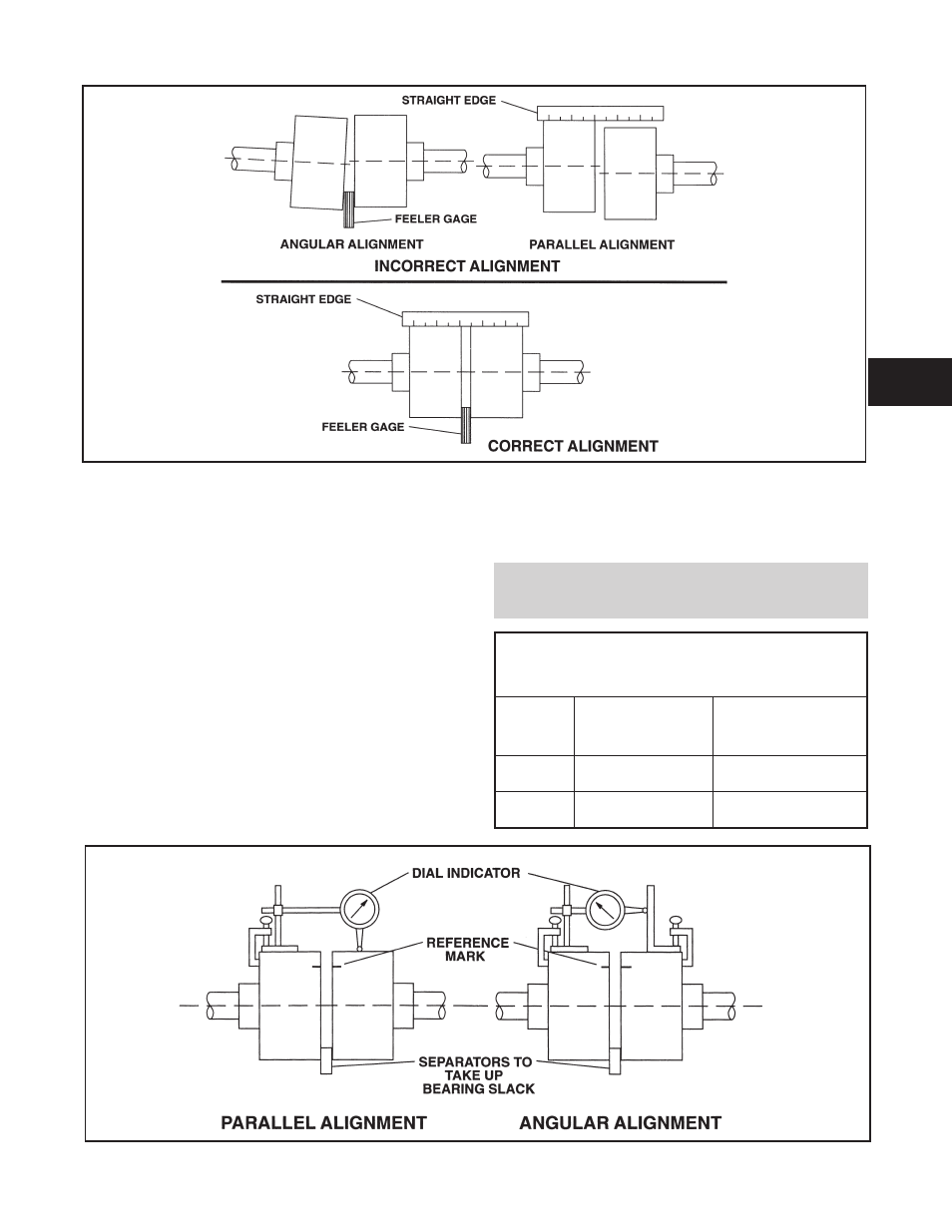
Method 2 - Dial Indicators (Fig. 12):
A dial indicator can be used to attain more accurate
alignment.
Fasten the indicator stand or magnetic base to the pump
half of the coupling and adjust the assembly until the
indicator button is resting on the other half coupling
periphery.
Set the dial to zero and chalk mark the coupling half where
the button rests. Also place a separator between the
coupling halves so bearing slack does not affect the
readings. (Chalk and separators are not necessary on the
elastomeric couplings that have not been disconnected.)
Rotate both shafts by the same amount; i.e., all readings
must be made with the button on the chalk mark.
The dial readings will indicate whether the driver has to be
raised, lowered or moved to either side. Accurate alignment
of shaft centers can be obtained with this method even
where faces or outside diameters of the coupling are not
square or concentric with the bores. After each adjustment,
recheck both parallel and angular alignments.
NOTE: Gross deviations in squareness or
concentricity may cause rotation unbalance problems
and if so must be corrected.
PERMISSIBLE COUPLING
MISALIGNMENT
Single Element
Coupling
Double Element
(spacer) Coupling
Parallel
.004” TIR
(4 mils)
.060” TIR
per foot of spacer length
Angular
.004” TIR
per inch of radius.
.002” TIR
per inch of radius
3410 IOM 1/2010
21
Fig. 10
Fig. 11
Fig. 12
3