Alignment, Warning, Alignment checks – Goulds Pumps 3410 - IOM User Manual
Page 22
ALIGNMENT
!
Alignment procedures must be followed to prevent
unintended contact of rotating parts. Follow
coupling manufacturer’s installation and operation
procedures.
s
!
WARNING
Before beginning any alignment procedure, make sure
driver power is locked out. Failure to lock out driver
power may result in serious physical injury.
Alignment is achieved by adding or removing shims from
under the feet of the driver and shifting equipment
horizontally as needed.
NOTE: Proper alignment is the responsibility of the
installer and user of the unit.
Accurate alignment of the equipment must be attained.
ALIGNMENT CHECKS
Initial Alignment (Cold Alignment)
•
Before Grouting Baseplate - To ensure alignment can
be obtained.
•
After Grouting Baseplate - To ensure no changes have
occurred during grouting process.
•
After Connecting Piping - To ensure pipe strains have
not altered alignment. If changes have occurred, alter
piping to remove pipe strains on pump flanges.
Final Alignment (Hot Alignment)
•
After First Run - To obtain correct alignment when
both pump and driver are at operating temperature.
Thereafter, alignment should be checked periodically
in accordance with plant operating procedures.
NOTE: Alignment check must be made if process
temperature changes, piping changes and or pump
service is performed.
Proper rough alignment must be made during unit setting
and grouting. See previous section.
There are two forms of misalignment between the pump
shaft and the driver shaft as follows:
1.
Angular misalignment — shafts have axis concentric
at intersection, but not parallel.
2.
Parallel offset misalignment — shafts have axis
parallel, but offset.
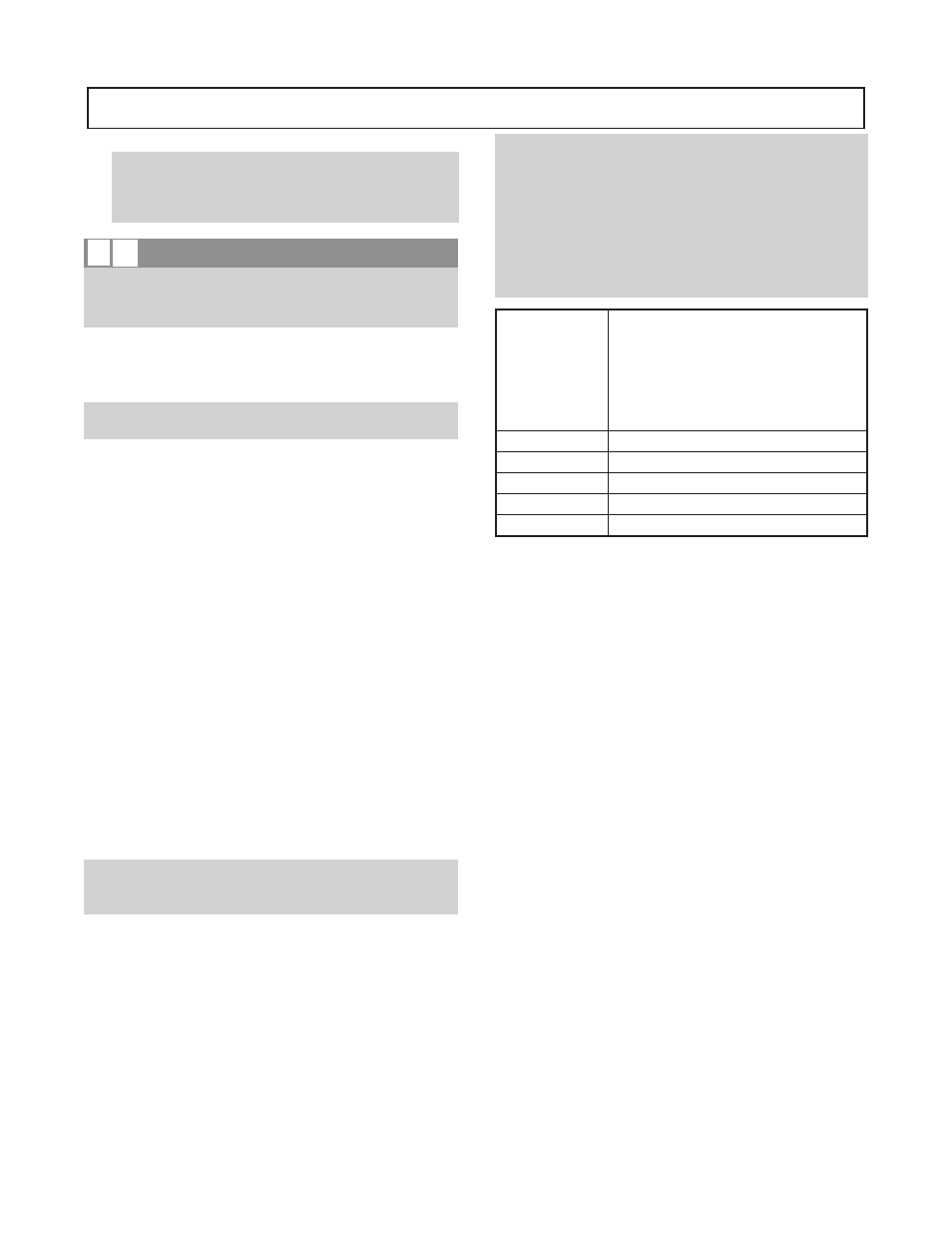
NOTE: During installation phase, however, it is
necessary to set the parallel alignment in the vertical
direction to a different critera due to the differences in
expansion rates of the pump and driver. Table 2 shows
recommended preliminary (cold) settings for electric
motor driven pumps based on different pumpage
temperatures. Driver manufacturers should be
consulted for recommended cold settings of other types
of drivers (steam turbines, engines, etc.)
Pumpage
Temperature
Above
Ambient
Temperature
Set Motor Shaft
Ambient
0.002" (0.005mm) - .004" (0.010mm) Low
100° F (38° C)
0.000" (0.0mm) - .002" (0.005mm) High
200° F (93°C)
0.004" (0.010mm) - .006" (0.15mm) High
300° F (149°C)
0.008" (0.020mm) - .010" (0.25mm) High
400° F (204°C)
0.012" (0.030mm) - .014" (0.35mm) High
The necessary tools for checking alignment are: (1) a straight
edge and a taper gauge or set of feeler gauges or, (2) a dial
indicator with mounting magnet and extension bars.
Check and correct for angular misalignment before correcting
parallel alignment. Final alignment should be made by moving
and shimming the motor on its base until the coupling hubs are
within the recommended tolerances measured in total run out.
All measurements should be taken with the pump and driver
bolts tightened. Final alignment check should be made after the
unit has attained its final operating temperature.
Method 1 - Using straight edge and taper gauges or feelers
(Fig. 11):
Proceed with this method only if satisfied that face and
outside diameters of the coupling halves are square and
concentric with the coupling bores. If this condition does
not exist or elastomeric couplings do not make this method
convenient, use Method 2.
Check for angular alignment by inserting the taper or feeler
gauges between the coupling faces at 90° intervals. The
unit is in angular alignment when these four (4)
measurements are the same, or within recommended
tolerances.
Check for parallel alignment by placing a straight edge
across both coupling rims on all four sides. The unit is in
parallel alignment when the straight edge rests evenly
across both coupling rims in all four (4) positions.
20
3410 IOM 1/2010
B
A