Dip switch settings & connector pinouts – Pathway # 8601, 8603, 8605 User Manual
Page 4
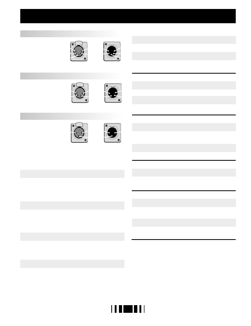
DIP SWITCH SETTINGS & CONNECTOR PINOUTS
WARRANTY
WARRANTY: Gray Interfaces products are carefully tested and inspected at the
factory and are warranted to be free from material and workmanship defects for a
period of one year from date of shipment. Seller's warranty shall be restricted to the
repair or replacement of any part that proves to be defective and for which a claim is
submitted to Seller before the expiration of the applicable warranty period, providing
that this warranty shall not apply to any defect arising from accident, misuse or
improper or unauthorized adjustment or repair. Seller will not assume any
responsibility for any labor expended or materials used to replace and/or repair any
equipment without Seller's prior written authorization. Freight terms on warranty
repairs are F.O.B. Seller's warehouse or factory. Collect shipments or freight
allowances will not be accepted without Seller's written authorization.
4
1 - COMMON
2 - CLOCK+
3 - ANALOG
4 - CLOCK-
1 - COMMON
2 - NC
3 - ANALOG
1 - COMMON
2 - DATA-
3 - DATA+
4 - NC
5 - NC
AMX - 192
STRAND D54 (384)
DMX - 512
IN (M)
OUT (M)
3
2
1
4
3
2
1
5
4
3
2
1
OUT (F)
IN (F)
5
4
3
2
1
PUSH
PUSH
4
3
2
1
PUSH
3
2
1
OPERATING MODE
STATUS QUO OPTION
CALIBRATE MODE
DUAL AMX OUTPUT
TEST CYCLE MODE
I/O MODE
S1-1
S1-3
S1-2
S1-5
S1-6
S1-7
S1-8
S1-4
BACKUP
STATUS QUO enabled
D/A OUTPUT CHECK enabled
DUAL AMX OUTPUT enabled
TEST CYCLE enabled
TEST CYCLE disabled
SINGLE AMX OUTPUT enabled
STATUS QUO disabled
D/A OUTPUT CHECK disabled
DMX input - DMX output
DMX input - AMX output
AMX input - AMX output
AMX input - DMX output
PILE-ON
MERGE
PM REV.6 9606
TEST MODE
ON
ON
OFF
ON
OFF
OFF
ON
OFF
ON
ON
ON
ON
ON
OFF
OFF
OFF
OFF
ON
ON
OFF
OFF
ON
OFF
OFF
A signal present on input A will have full control of the output, and any signal at
input B will be ignored. If the A signal is lost, the output will be controlled by
input B. The address switches will offset both inputs.
Output data remains active at last valid levels for 5 minutes
Analog output level (5.0V) can be checked at the AMX output (pin 3)
DC voltmeter; no other functions are active
using a
Ramps the selected dimmer up and down continuously between zero and
full when in test mode
The selected dimmer is set to full when in test mode
Output data fails 2 seconds after loss of input data
Signals present at both inputs will have control of the output. The highest level
on any individual device channel on either input will be in control of the output
level. The address switches will offset both inputs.
Input B is appended to input A to create one continous output consisting of the
total numer of device channels on both inputs. The address switches will offset
input B only.
INPUT TEST: Receive data LEDs indicate correct data signal (on steady), faulty
or incorrect signal (flashing), or absence of any signal (off).
OUTPUT TEST: The selected protocol is transmitted and the device channel
assigned by the address switches is set to full or cycled as per switch S1-8.