Pathway #1003 eDIN Contact Closure Interface User Manual
Model 1003 contact closure manual, Status indicators connections, Overview
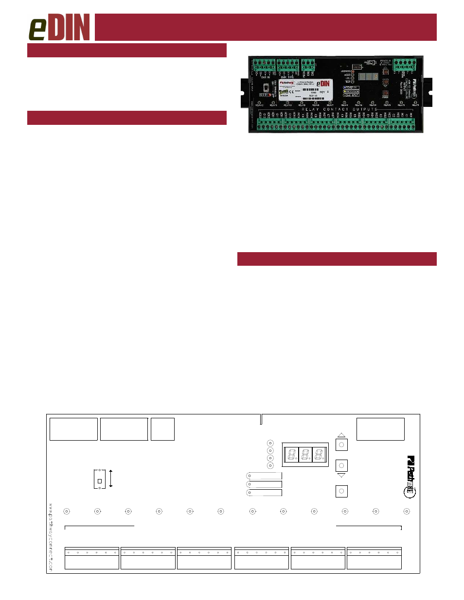
Model 1003 Contact Closure
Manual
STATUS INDICATORS
CONNECTIONS
POWER IN
Blue. Glowing steadily indicates power
supply OK; off indicates no power.
PROCESSOR Green. Glowing steadily indicates proces-
sor is OK; off when POWER IN is lit indi-
cates processor failure.
DMX
INPUT
Amber. Glowing steadily indicates data
signal received; off indicates no signal
present.
RELAY
Red. Glowing steadily indicates relay is
energized. Flickers for momentary action.
FUNCTION
Amber. Indicates the function associated
with the numeric display.
OVERVIEW
Pathway eDIN Contact Closure outputs provide
DMX-controlled form-C relay switch closures for
both power and signal level switching. The card
is RDM discoverable and configurable. The DIN
form factor makes installation fast and easy.
eDIN Contact Closures Interfaces feature terminal strips
that can be removed from the card to facilitate easy wire
installation or replacement. Make the following connec-
tions, WITH THE POWER TURNED OFF:
POWER
This interface is designed to run on a range of voltages
from 9-30 volts DC. Each module requires 400mA.
Observe the correct polarity when connecting to V+ and
V-. A second set of terminals are provided to connect to
other eDIN modules. The EARTH GROUND terminal
must be connected to the enclosure’s chassis or electrical
ground terminal to ensure EMC compliance.
DMX
DMX connections consist of a shield and a data pair. A
optional second auxiliary data pair is also occasionally
employed. DMX IN usually comes from a control console,
architectural controller or opto-splitter. DMX THRU pro-
vides a means to daisy-chain DMX to other eDIN mod-
ules. Connect DATA+ and DATA-, to D1+ and D1-. Ob-
serve the same polarity convention throughout the sys-
tem. Connect the cable shield or common to the SHLD
COM terminal.
DMX PRESENT RELAY CLOSURE
Starting with firmware 1.5.5, the J13 DMX present relay
closure is supported. Wire RCOM to RNO or RNC for
normally open or normally closed, as desired.
CONTACT OUTPUTS
The eDIN contact closure interface can be thought of as
twelve DMX controllable switch closures. As switches,
they need two connections each since the switches pro-
vide no voltage or current on their own. One connection is
to the supply and one goes to the load. The switch clo-
sures are provided by twelve relays. Each relay has three
sets of contacts; normally open (NO), normally closed
(NC) and common (C). Generally the normally open con-
tacts are what are used, providing an open switch that
closes when the relay is energized. Normally closed con-
tacts operate in the opposite manner, providing a closed
switch that opens when the relay is energized.
All common terminals are independent of one another.
N
C
1
O
U
T
P
U
T
C
O
N
T
A
C
T
C
L
O
S
U
R
E
e
D
IN
1
2
C
H
A
N
N
E
L
RELAY5
R E L A Y C O N T A C T O U T P U T S
C
1
1
C
9
RELAY6
RELAY1
RELAY2
RELAY3
RELAY4
RELAY7
RELAY8
RELAY9
RELAY10
RELAY11
RELAY12
N
O
1
C
1
N
O
2
C
2
N
C
2
N
O
3
C
3
N
C
3
N
O
4
C
4
N
C
4
N
O
5
C
5
N
C
5
N
O
6
C
6
N
C
6
N
O
7
C
7
N
C
7
N
O
8
C
8
N
C
8
N
O
9
N
C
9
N
O
1
0
C
1
0
N
C
1
0
N
O
1
1
N
C
1
1
N
O
1
2
C
1
2
N
C
1
2
POWER IN
PROCESSOR
TEST
UTIL
MODE
ADDRESS
ENTER
O
N
T
E
R
M
IN
A
T
E
D
M
X
DMX INPUT
DMX IN
R
e
v
.4
POWER IN
O
F
F
DMX THRU
DMX
PRESENT
RELAY