About the interface, Address selection, 5v reg – Pathway # 8601, 8603, 8605 User Manual
Page 3: Dc-dc conv
X 100 X 10
X 1
made in Canada
address select
mode select
pow
e
r
data
A
data
B
5
4
3
2
1
6 7 8
1
2
3
4 5 6
7
8
90
1
2
3
4 5 6
7
8
90
1
2
3
4 5 6
7
8
90
2
3
1
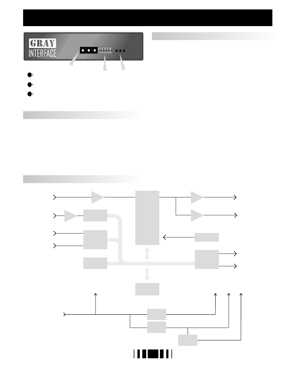
Address select rotary switches
Mode select DIP switches
LED indicators: power, data A and data B
1
2
3
D M X M a n g e r
BLOCK DIAGRAM
LED INDICATORS
ABOUT THE INTERFACE
3
ADDRESS SELECTION
Three rotary switches select the offset start address for the unit in most
configurations. For dual AMX output, the address switches select the
starting dimmer number for the second AMX output line. In merge
mode, the switches set the starting address for the second input data
line. In test mode, the switches set dimmers to full one at a time. From
left to right the switches are set as hundreds, tens, and ones.
Three LEDs are used to indicate, from left to right, power supply /
processor run status, data A receive detect, and data B receive detect.
In test mode the receive detect LEDs will flash if the input signal is not
as selected by the I/O mode switches or if the signal is unrecognizable.
POWER : Glowing solidly indicates power supply and
processor OK; off indicates no power, and
flashing indicates defective processor or
control logic.
DATA A : Glowing solidly indicates data signal A received;
off indicates no input signal present.
DATA B : Glowing solidly indicates data signal B received;
off indicates no input signal present.
+5V
REG
DC-DC
CONV.
-5V
REG
+5V -12V
+12V
-5V
DC
POWER
INPUT
ADDRESS
AND
DIP SWITCHES
DIGITAL
TO
ANALOG
WATCHDOG
TIMER
AMX1 ANALOG OUT
AMX2 ANALOG OUT
RESET
ADDRESS/ DATA BUS
DMX DATA OUT
AMX CLOCK 1 OUT
DMX DATA OUT
AMX CLOCK 2 OUT
ANALOG
TO
DIGITAL
UART
AMX1 ANALOG IN
AMX2 ANALOG IN
DMX DATA B IN
DMX DATA A IN
AMX CLOCK IN
MICRO
PROCESSOR
MEMORY