Pathway #1004 eDIN DMX-to-Analog Interface User Manual
Model 1004, Dmx demultiplexer manual, Rev5
Model 1004
rev5
• DMX Demultiplexer Manual
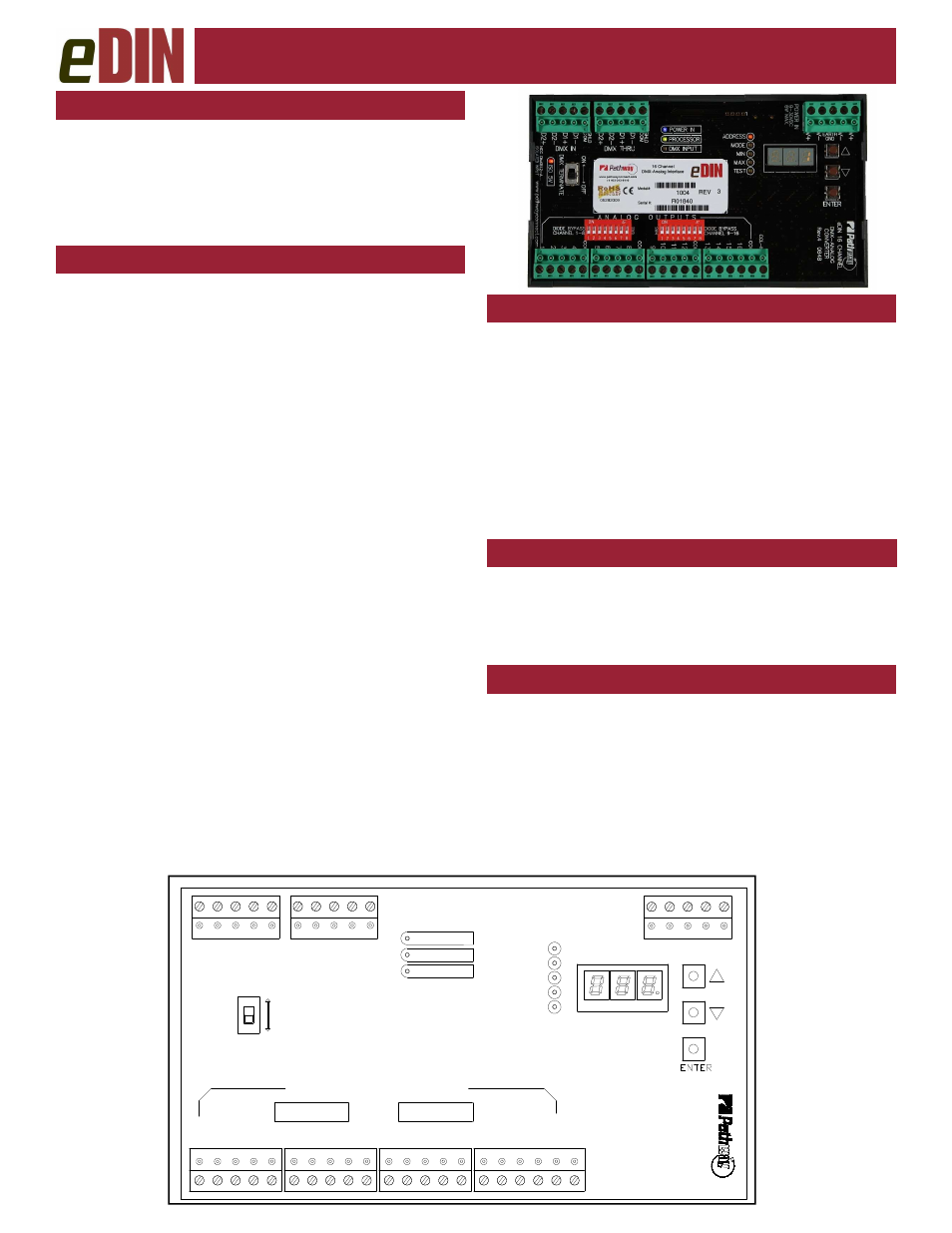
STATUS INDICATORS
CONNECTIONS
POWER IN
Blue. Glowing steadily indicates power
supply OK; off indicates no power.
PROCESSOR Green. Glowing steadily indicates proces-
sor is OK; off when POWER IN is lit indi-
cates processor failure.
DMX
INPUT
Amber. Glowing steadily indicates data
signal received; off indicates no signal
present.
FUNCTION
Amber. Indicates the menu function asso-
ciated with the numeric display.
OVERVIEW
Pathway eDIN Demultiplexer converts DMX512
signals into 16 channels of analog control voltage.
The Demultiplexer can also control Mark 7–type
fluorescent ballasts, solid state relays or LEDs.
The module is RDM discoverable and configurable.
The eDIN Demultiplexer features terminal strips that can
be removed from the card to facilitate easy wiring installa-
tion or replacement. Make the following connections,
WITH THE POWER TURNED OFF.
POWER
The Demultiplexer will operate on a range of voltages
from 9-30 volts DC. Each eDIN module requires 250mA.
Observe the correct polarity when connecting to V+ and
V-. A second set of terminals are provided as a thru con-
nection to other eDIN modules. The EARTH GND termi-
nal must be connected to the enclosure’s chassis or elec-
trical ground terminal to ensure EMC compliance.
DMX
DMX connections consist of a shield and a data pair. A
optional second auxiliary data pair is also occasionally
employed. DMX IN usually comes from a control console,
Pathport
®
node, architectural controller or opto-splitter.
DMX THRU provides a means to daisy-chain DMX to
other eDIN modules. Connect DATA+ and DATA- to D1+
and D1-. Observe the same polarity convention through-
out the system. Connect the cable shield or common to
the SHLD COM terminal.
ANALOG OUTPUTS
Sixteen analog output terminals are provided in groups of
four, each with a common terminal. All common terminals
are internally connected, so only one needs to be tied to
the device being controlled. Outputs are rated up to 15
volts DC, 10mA per channel. Maximum wire run is 150
meters (500 ft.).
DMX TERMINATE
DMX rules require the final device in line have a terminat-
ing resistor. If no devices or modules are connected to the
DMX THRU terminal, the DMX TERMINATE switch
should be ON. If other devices or modules are connected
to DMX THRU, the DMX TERMINATE should be OFF.
CONFIGURATION
To configure, first press the
▲
or
▼
buttons to select the
desired function, as indicated by a lit LED next to AD-
DRESS, MODE, MIN, MAX, or TEST. Once chosen,
press and hold the ENTER button until a dot appears on
the right hand display. The function is now editable.
When done editing a parameter, press ENTER. The
dot will disappear, the new value will be saved and the
unit will be ready for operation.
MODE
DIODE SHUNT
CHANNEL 9-16
T
E
R
M
IN
A
T
E
A N A L O G O U T P U T S
DIODE SHUNT
CHANNEL 1-8
O
F
F
D
M
X
O
N
POWER IN
DMX INPUT
PROCESSOR
R
e
v
.4
e
D
IN
1
6
C
H
A
N
N
E
L
D
M
X
-
A
N
A
L
O
G
C
O
N
V
E
R
T
E
R
MAX
TEST
MIN
ADDRESS
DMX THRU
DMX IN
D
2
-
D
2
+
D
1
-
D
1
+
D
2
+
S
H
L
D
C
O
M
D
2
-
D
1
+
C
O
M
S
H
L
D
D
1
-
C
O
M
3
2
1
4
C
O
M
3
2
1
4
C
O
M
3
2
1
4
C
O
M
3
2
1
4
C
C
L
-IN
V
-
V
+
GRD
V
+
V
-
6
W
a
tts
M
A
X
9
-3
0
V
D
C
P
O
W
E
R
IN