Installer’s guide – Pathway Pathport Installers Guide User Manual
Page 4
Installer’s Guide
4
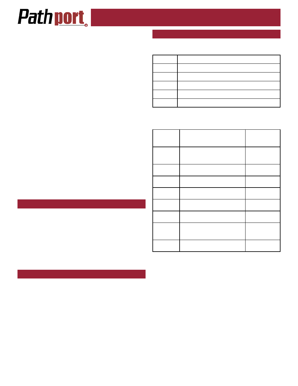
This chart is based on the current ESTA draft standard
BSR E1.27-2 and is intended for DMX cabling - NOT
DMX-over-Ethernet cabling. This pinout chart should NOT
be used for wires carrying Ethernet signals or DMX-over-
Ethernet protocols.
Great care must be taken to prevent the accidental con-
nection to non-DMX equipment.
The connection of DMX equipment to non-DMX equip-
ment such as Ethernet switches may result in serious
equipment damage.
To help prevent this possibility, unless the wires have
another known usage in the existing installation, wires 4
and 5 should be capped and turned back rather than con-
nected.
The use of RJ45 connectors for DMX equipment should
be restricted to patch bays in access controlled rooms
and should not be used for the direct connection of port-
able equipment.
As each node is installed, remove one of the additional
serial number stickers and place it on the Installation Re-
cord Sheet included with each Uno. Write down the loca-
tion, jumper settings and any other comments. A second
sticker can be placed on the face of the Uno for identifica-
tion during commissioning. This sticker can be easily re-
moved and discarded when no longer needed.
Once this information is recorded, check the backbox
for obstructions or foreign material. The backbox should
be clean and empty. Make sure there is a RJ45 female
punchdown connector (preferred) in the box or a male
RJ45 pigtail.
Inspect the Uno and make sure all components are se-
curely fastened and that the printed circuit boards are in-
tact.
If the back backbox contains an RJ45 female punch-
down connector, use a male-to-male jumper to connect it
to the node. Otherwise, plug the male RJ45 pigtail di-
rectly into the connector on the back of the node. Attach
the green ground wire to the ground screw in the back-
box.
Gently insert the Uno straight into the backbox and
screw it into place with the long mounting screws pro-
vided. Place the cover plate over the installed Uno and
use the two short screws to fasten the cover plate. Do
not over-tighten these screws.
When the network switch or in-line injector is turned on,
the Uno will power up. Remember, the Uno will only op-
erate on Power-over-Ethernet.
TESTING THE INSTALLATION
Once all connections are made and inspected for er-
rors, power up the Ethernet switches on the network. The
Pathports should boot up and, except for the Uno, display
their IP address or node name, if configured. The NET
LED will illuminate on the Uno, showing that it has power.
The appropriate lights on the Ethernet switches should
also light up.
At this point, refer to the Pathport Manager Software
User Manual for system configuration and protocol selec-
tion.
LOCAL POWER
All C-series, D-series and R-series nodes can be con-
nected to an external power supply, for situations where
Power-over-Ethernet is not available. Each node will re-
quire a supply between 18 and 50VDC and consume 4
watts of power.
With the power supply turned off, connect the bare wire
ends to the 2-wire terminal block (included). Slip the
block over the pins marked V+ and V-, observing polarity.
On C- and D-series nodes, these pins are mounted on the
circuit board. On R-series nodes, the connector is on the
back face of the unit. Check all wiring, then connect the
power supply to the mains power. The node should boot
up.
Wire color is manufacturer-specific. Use the connector
to determine pin number for each wire.
DMX XLR CONNECTOR WIRE TERMINATION
XLR Pin Standard RS422/485 Wire Conductor
Pin 1
Shield
Pin 2
Data – (pair 1 complement)
Pin 3
Data + (pair 1 true)
Pin 4
Optional Data – (pair 2 complement)
Pin 5
Optional Data + (pair 2 true)
Wire
Colour
and #
Function
XLR Pin
Number
White/
orange
(1)
Data + (pair 1 true)
3
Orange
(2)
Data –
(pair 1 complement)
2
White/
green (3)
Optional Data +
(pair 2 true)
5
Green
(6)
Optional Data –
(pair 2 complement)
4
Blue
(4)
Unassigned
White/
blue (5)
Unassigned
White/
brown
(7)
Data signal common for
Pair 1
1
Brown
(8)
Data signal common for
Pair 2
1
The following is the termination for Cat5 cable, when
used for DMX.