Installer’s guide – Pathway Pathport Installers Guide User Manual
Page 2
Installer’s Guide
2
OPERATING ENVIRONMENT
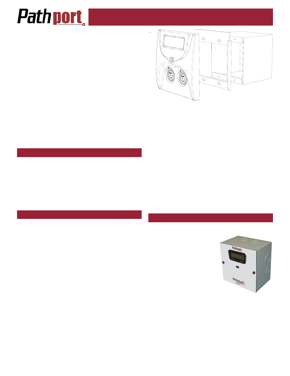
D-SERIES NODE INSTALLATION
this feature, often called Inter Group Management Proto-
col (IGMP) should be turned off.
Other security features of the managed switch should
be examined. Most will not be necessary on a lighting
network and should be disabled. At the very least, this
will help keep the through-put speeds of the switch as
high as possible.
One feature that managed switches can provide that
unmanaged switches cannot is redundancy. Managed
switches can be configured to work around a problem or
even to activate a redundant leg of the network. In some
applications, this feature may be sufficiently desirable to
offset the added configuration time and expense.
For unmanaged and plug-and-play switches, the feature
sheets must be carefully examined to ensure broadcast
storm and IGMP filtering are not permanently turned on.
Switches should be connected to an uninterruptible
power supply (UPS) with power conditioning. A UPS al-
lows for orderly shutdown in case of power failure, and
protects against spikes and brown-outs, which can cause
memory corruption or physical damage to the nodes.
All Pathport nodes are designed for indoor use in a dry
location. To maximize equipment life and minimize unreli-
ability and sudden failure, the following environment
should be maintained:
•
ambient temperature extremes: -10 to +50 degrees C
•
operating temperature: 0 to +40 degrees C
•
relative humidity: 10 – 95%, non-condensing
•
general conditions: clean, dust-free
C-SERIES NODE INSTALLATION
Disconnect all power before proceeding with the instal-
lation.
C-series nodes are designed to be installed in re-
cessed, standard two-gang masonry deep backboxes
(ears in) for flush-mounting or, for surface mounting, in
Pathport surface mount backboxes, part number 6901.
Use of other surface mount backboxes is not recom-
mended.
If the node has been pre-configured, check the tempo-
rary label to ensure the node is being installed in the cor-
rect location.
Check the installed backbox for obstructions or any for-
eign material. The backbox should be clean and empty.
Make sure there is a RJ45 female punchdown connector
in the box (preferred) or a male RJ45 pigtail. Install the
in-line jack provided, if necessary.
Attach the Pathport trim ring to the backbox with the 4
screws provided. Do not over-tighten or do anything that
will distort the shape of the trim ring.
Inspect the node and make sure all components are
secure and that the printed circuit boards are secure.
Note that it is normal to see exposed metal on the mating
connectors.
If the backbox contains an RJ45 female punchdown
connector, use the male-to-male jumper (included) to con-
nect it to the node. Otherwise, plug the male RJ45 pigtail
directly into the connector on the back of the node. At-
tach the green ground wire to the ground screw in the
backbox.
If local power is required for the node, see the note on
local power at the end of this guide.
Gently insert the node straight into the backbox, lifting it
slightly so that is high in the backbox. Once all the way in,
lower it slightly until the tabs at the top of the trim ring
take hold of the face plate. Once the top of the node’s
faceplate is retained, swing the bottom in tight to the wall.
Make sure no wiring or connectors are pinched or exces-
sively bent or stressed. Using a #0 Phillips driver (not
included), tighten the two setscrews provided, one on
each side of the node’s face, to complete installation. If
the nodes have shipped with hex-head set screws, in-
stead use a 1/16” Allen key (not provided)
The node is ready to be powered up.
Disconnect all power before proceeding with installa-
tion.
D-series nodes are surface-
mount enclosures designed for
conduit-enclosed cabling con-
nection to permanently installed
equipment such as dimmers
and relay cabinets. D-series
nodes are shipped attached to
their backboxes.
First, remove the two screws
holding the faceplate to the
backbox. Keep the screws for
later use. Gently remove the faceplate and attached
printed circuit boards. Put the faceplate in a safe and
clean location, such as back into its shipping container.
Determine the location of the backbox in relation to the
incoming and outgoing conduit lines. Remove the appro-
priate knockouts then securely mount the backbox to the
wall using appropriate fasteners. If the backbox must be
installed prior to the completion of the conduit and wiring
runs, then label the backbox and the container holding the
removed faceplate and store the container in a safe loca-
tion. Make sure the two faceplate screws are stored in