Rtb terminal block, Pin description, Fnio s-series – Beijer Electronics NA-9379 User Manual
Page 18
18
MODBUS Programmable I/O NA-9379
FnIO S-Series
Copyright(C) CREVIS Co.,Ltd Support +82-31-899-4599 URL : www.crevis.co.kr
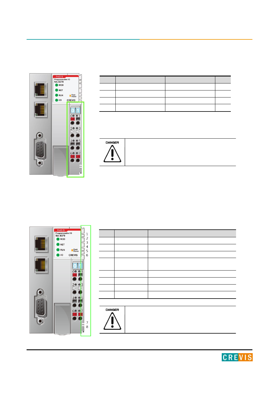
3.5. RTB Terminal Block
- System Power: The power for starting up CPU.
- Field Power: The power for input and output line.
Do not use an incorrect voltage/frequency!
The use of an incorrect supply voltage or frequency
can cause severe damage to the component.
3.6. Pin Description
Communication between the Network adapter and the expansion module as well as system / field power supply of the
bus modules is carried out via the internal bus. It is comprised of 6 data pin and 2 field power pin.
Do not touch data and field power pins in order to
avoid soiling and damage by ESD noise.
Pin
Signal Description
Signal Description
Pin
0
System Power 24V
System Power 0V
1
2
F.G
F.G
3
4
Field Power 0V
Field Power 0V
5
6
Field Power 24V
Field Power 24V
7
No.
Name
Description
1
System Vcc
System supply voltage (5V dc).
2
System GND
System Ground.
3
Token Output
Token output port of Processor module.
4
Serial Output
Transmitter output port of Processor
module.
5
Serial Input
Receiver input port of Processor module.
6
Reserved
Reserved for bypass Token.
7
Field GND
Field Ground.
8
Field Vcc
Field supply voltage (24Vdc).