Vaddio WallVIEW HD-22 and WallVIEW HD-30 User Manual
Page 9
WallVIEW HD-22 and HD-30 SR Systems
WallVIEW HD-22 and HD-30 SR Cameras Systems - Document Number 342-0643 Rev A
Page 9 of 20
Q
UICK
-C
ONNECT
SR
I
NTERFACE
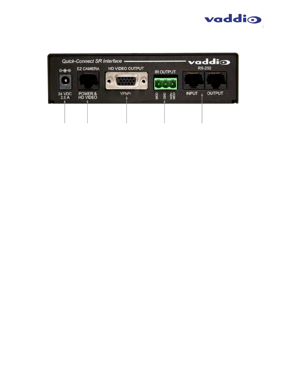
Image: Rear Panel with Feature Call-outs
1) Power Input:
5.5mm OD x 2.5mm ID coaxial connector for the provided 24 VDC, 2.0 Amp switching power supply.
2) EZCamera Power & HD Video:
A single Cat-5 connection between the EZCAMERA POWER & HD VIDEO RJ-45 connector and the camera’s
EZ Power HD Video Port on the HD-19 camera extends power and video. Power is fed to the camera and HSDS
video is returned from the camera on the same Cat-5.
3) HD Video Output:
DE-15 connector outputs the YPbPr analog component HD video, which was extended from the camera over
Cat-5 cable. SD video resolutions (Y/C and CVBS formats) are not supported by the Quick-Connect SR
Interface, however analog component SD (high fps format - 480p/59.94 and 576p/50) video is supported.
4) IR Output:
With the IR pass-thru turned ON (see camera dip switch settings), IR from third-party IR remote controls can be
sent through the camera to third-party equipment, such as hardware videoconferencing codecs. IR can be used
as either modulated (through the air) or non-modulated (wired) signals).
5) RS-232 Input & Output Jacks:
These RJ-45 connectors allow an external controller (look-out for upcoming shameless plug) like the
ProductionVIEW™ Precision Camera Controller to route through the Quick-Connect SR for ease of cable routing.
Before Installing:
Choose camera mounting location, paying close attention to camera viewing angles, lighting conditions,
possible line of site obstructions, and checking for in-wall obstructions where the camera is to be mounted.
Always pick a mounting location that will optimize the performance of the camera.
The wall mount for the WallVIEW system can be mounted directly to a 2-gang wall box or can be mounted
using only dry wall anchors.
For Power/Video and RS-232 signals, use standard Cat-5 cable (568B termination with real RJ-45
connectors) from the EZ-POWER VIDEO and RS-232 ports on the back of the camera to the Quick-Connect
SR Interface (see install instructions).
①
②
④
⑤
③