Vaddio WallVIEW HD-20 DVI/HDMI User Manual
Page 4
WallVIEW DVI/HDMI HD-20
WallVIEW DVI/HDMI HD-20 Manual 342-0180 Rev. D
Page 4 of 20
UNPACKING:
Carefully remove the device and all of the parts from the packaging.
Unpack and identify the following parts for 999-6956-000:
One (1) ClearVIEW HD-20 HD Camera
One (1) Vaddio IR Remote Commander
One (1) Quick-Connect DVI/HDMI SR Interface One (1) Laird Technologies 28A2432-0A2 Clamp-on Ferrite Cylinder (Wrap IR forwarding
LED wires twice before screwing stripped wire ends to 3 conductor Molex Euro Jack)
Two (2) Laird Technologies 28A0640-0A2 Clamp-on Ferrite (Clamp around 0.8" diameter DVI Cable at the Quick-Connect DVI end)
One (1) Laird Technologies HFA163090-0A2 Clamp-on Ferrite (Clamp around 0.8" diameter shielded DVI Cable at the Monitor end)
One (1) Vaddio PowerRite™ 24 VDC, 2.0 Amp Power Supply
One (1) 998-1001-232 EZCamera Control Adapter (for control systems)
One (1) 998-1002-232 EZCamera Control Adapter (for TANDBERG VC systems) One (1) 3-pos Phoenix type connector
One (1) CONCEAL Wall Mounting System with Mounting Hardware
One (1) AC Cord Set for North America
Documentation
(Note: The 999-6956-001 Int’l Version includes the Euro and UK power cables)
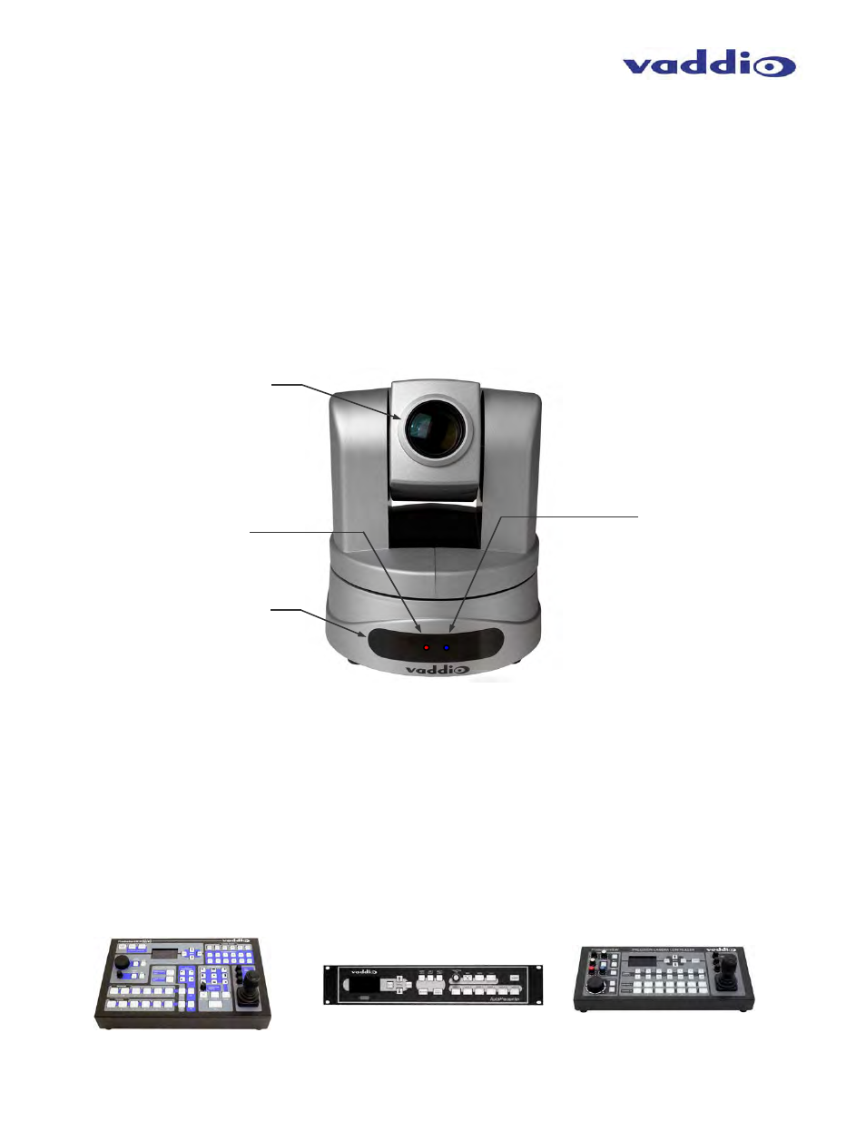
ClearVIEW HD-20 PTZ Camera, Front View with Feature Call-outs:
1) Camera and Zoom Lens:
The 20X optical zoom lens is built around a 6.49mm diagonal (1/2.8 Type) high-speed CMOS image sensor with
a total of 3.27M pixels for truly precise HD video image acquisition.
2) Red Tally Light:
A red tally light is illuminated when the camera receives a VISCA command from an external control system.
3) IR Sensors:
IR sensors are built into the front of the ClearVIEW HD-20 to receive IR signals from the IR remote control
supplied with the camera.
4) Blue Power Light:
A Vaddio blue power light is illuminated when the camera is turned on.
Compatible Vaddio Switchers and Joystick Controllers:
ProductionVIEW™ HD
(999-5600-000)
Precision Camera Controller
(999-5700-000)
AutoPresenter
(999-5675-000)
②
①
③
④