Vaddio WallVIEW HD-20 DVI/HDMI User Manual
Page 11
WallVIEW DVI/HDMI HD-20
WallVIEW DVI/HDMI HD-20 Manual 342-0180 Rev. D
Page 11 of 20
Step 8:
Connect the HD Video Outputs (DVI or HDMI with adapter cable - or - analog HD YPbPr video) into a
display device or video console. Please make sure that the video console or the display device is set up to
receive the HD camera resolution that was chosen with the rotary switch on page 6. Most monitors are
automatic, however all consoles will need set-up prior to termination.
Step 9:
Connect the Vaddio 24 VDC, 2.0A power supply to the POWER Connector on the Quick-Connect and
plug the power adapter into an AC outlet. Power will travel down the Power/Video Cat-5e cable to the camera.
The camera will “Home” to a centered position, return HSDS video back to the Quick-Connect and is ready for
control from the IR remote or RS-232 camera controller. Boot Order: Always turn the cameras on first, then
the controller or codec.
Daisy Chain Configurations/Installation Instructions:
In some cases, daisy chain control situations just can’t
be avoided. Because of this, Vaddio added “Daisy Chain Control Emulation” or DCCE™ to the Quick-Connect
DVI/HDMI - SR Interface in order to use the HD-20 camera in these situations. See Connectivity Example 2
(previous page) where the codec requires daisy chain control wiring.
1) For daisy chain control, first complete steps above, since all the cabling between the camera and the Quick-
Connect DVI/HDMI Interface is the same.
2) Instead of running a cable from the 1
st
camera to the 2
nd
camera, run a Cat-5e patch cable from the 1
st
Quick-
Connect DVI/HDMI Interface’s RS-232 CONTROL DAISY CHAIN RJ-45 jack, to the 2
nd
Quick-Connect DVI-
HDMI SR Interface’s RS-232 CONTROL INPUT RJ-45 jack.
3) Within the modified VISCA® protocol that the codec and the HD-20 use, the 1
st
in the chain will set up as
Camera #1, the second will set up as Camera #2 in the chain, allowing the codec IR remote to select which
camera it will switch to and which to control.
4) In the case of TANDBERG codecs, use the IR Modulated output of the Quick-Connect and a Xantech IR
emitter (282D or 283D) and attach the emitter to the front panel of the codec (in front of the IR receiver).
5) Polycom codecs with IR receivers can connect the IR feed-through the same way as the TANDBERG, but do
not use daisy chain control. Several Polycom codecs can also be connected directly with the non-modulated
signal to the codec’s IR signal input port.
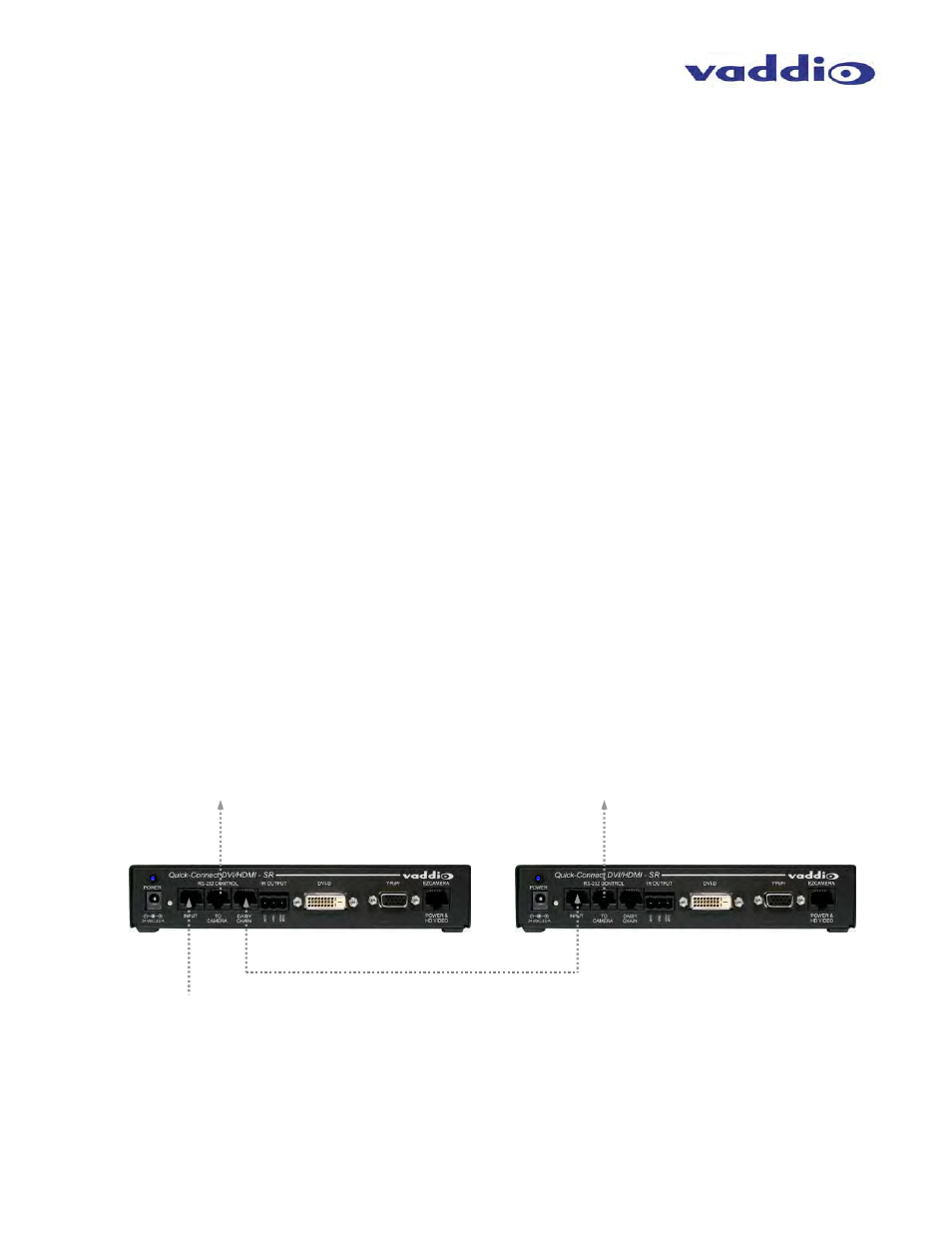
Basic Daisy Chain Connectivity:
RS-232 from Codec
Single Control Port
Daisy Chain Port Out
RS-232
To Camera
#2
RS-232
To Camera
#1
RS-232 Control IN
RS-232