Vaddio TRIO Solutions User Manual
Page 9
TRIO I/O and TRIO Mic Solutions
Vaddio TRIO MIC Solutions - Document Number 342-0568 Rev A
Page 9 of 16
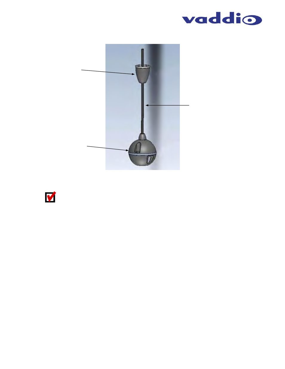
Diagram: TRIO Ceiling Mic Array Head
1) Trim
Cover:
The trim cover screws onto the 5/8” feed-through coupler on the Ceiling Interface Module
providing a dressed appearance for ceiling installations. An escutcheon ring is provided to trim out the hole.
Remember to keep the pilot hole in the tile or drywall as close to 5/8” as possible
2) Array
Head Drop Cable: A 36” cable terminated with a RJ-45 jack and provides the connection of the
ceiling mic array head with the processing board housed in the Ceiling Interface Module.
3) Array
Head:
The array head is 2.5” diameter microphone that provides 360 degree sound pick-up coverage.
TRIO
MIC
I/O
S
YSTEM
C
ONFIGURATION AND
P
ROGRAMMING
The TRIO Mic I/O is a plug & play device that requires no programming. However, a there are a few
recommendations when interfacing to the audio mixer:
TRIO Mic Audio Levels: The recommendation is to set the input gain on the external audio mixer level during
speech to peak at @ +6dBu.
AEC Reference Audio Level: The AEC Reference output level from the audio mixer going to the TRIO MIC I/O
should be set at a nominal level @0dBu. An extremely low level AEC Reference (<-20dBu) could impact the
AEC performance it the TRIO mic arrays.
The Room’s Audio Mixer: The TRIO Microphones are recommended to be used with professional audio mixers
that have automatic microphone mixing functions. The automatic microphone mixer will yield better far-end audio
quality when multiple TRIO Microphones are used within the same room installation.
➌
➊
➋