Vaddio DomeVIEW Indoor Pendant Mount User Manual
Page 5
Vaddio DomeVIEW Indoor Pendant Mount Dome Installation and User Guide - Document 341-444 Rev. C
Page 5 of 12
Canon VC-C50iR Camera only:
5) Attach the EZCamera Cabling Shoe, (4) in Figure 2, to the Canon VC-C50iR.
a. When mounting the Canon VC-C50iR without the EZCamera cabling system - skip this step.
6) Attach the camera (3) to the camera mounting stage (6) with two 8-32 x .5” pan head screws (2) and two
#8 lock washers (see Figure 2). Skip to step 11.
Sony EVI-D70 Camera only:
7) Image Flip Switch, IR Select Switch and other Mode switches (set switches prior to powering up camera)
a. Set the Image Flip dipswitch on the back of the EVI-D70 camera to the ON position. The
camera will be inverted in the dome enclosure and the image needs to be flipped.
b. When using the IR Remote control in an environment with multiple cameras, set the IR Select
Switch frequency setting to 1, 2 or 3 to avoid having the IR remote control more than one
camera at a time.
c. Check the full-length manual for the EVI-D70 camera for other mode switch settings. The
manual is available on the Vaddio website (www.vaddio.com).
8) Attach the EZCamera Cabling Shoe, (4) in Figure 3, to the Sony EVI-D70 camera.
a. When mounting a Sony EVI-D70 without the EZCamera Cable System - skip this step.
9) Attach the Camera Base Plate (9) to the camera (3) with the provided ¼”-20 x .5” screw (10).
10) Attach the camera (3) and camera base plate (9) to the camera mounting stage (6) with four 8-32 x .5”
pan head screws (2) and four #8 lock washers (see Figure 3).
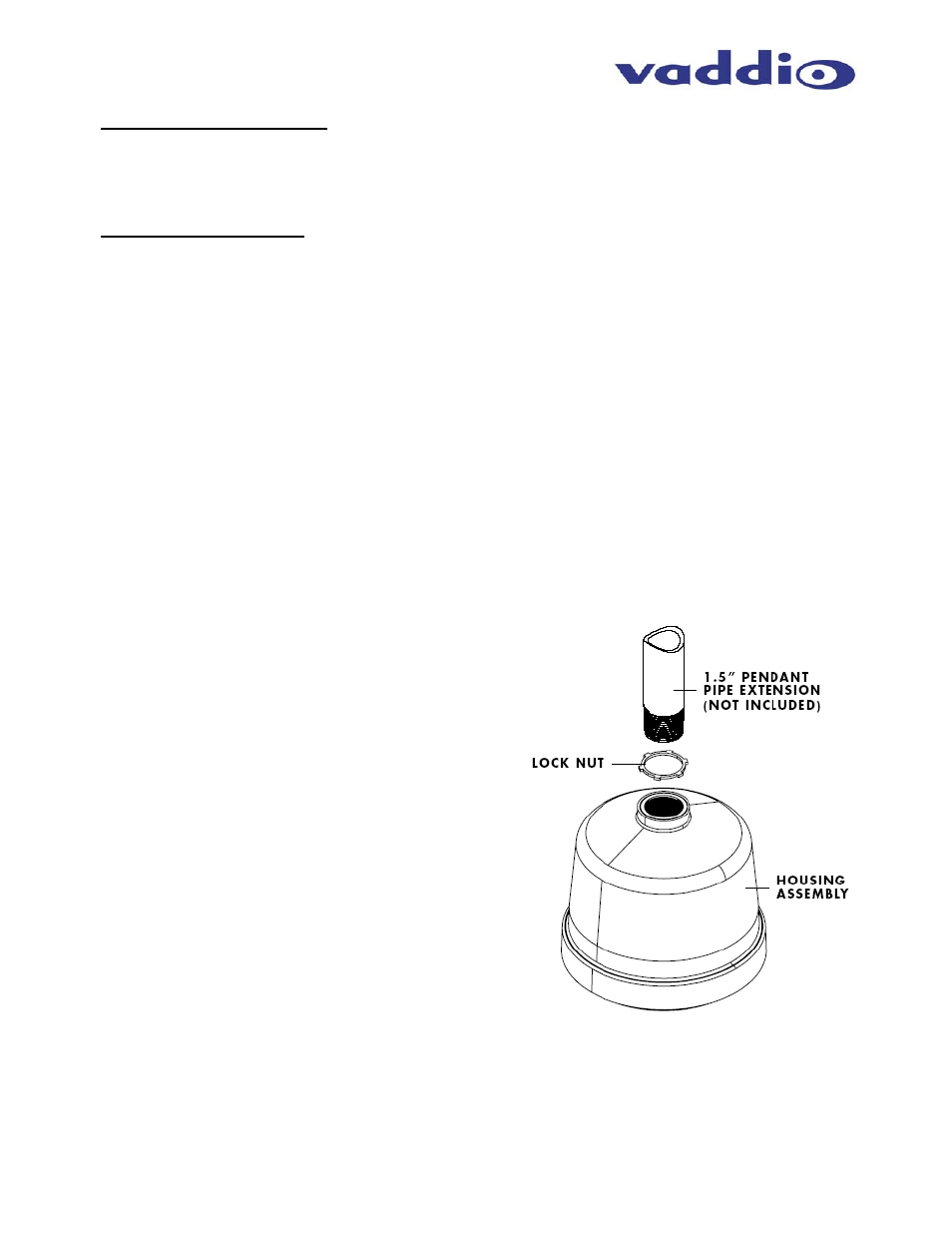
Installing the dome to a pendant mount or pipe extension:
When the camera is mounted in the dome enclosure, the dome can be mounted to a 1-1/2” NPT pipe
extension attached to the Vaddio Ceiling Pendant Mount (part # 998-9300-002) or Curved Wall Mount (part #
998-9300-000). These mounts are sold separately. To install the dome to a 1-1/2” NPT Pipe Extension or to
a 1-1/2” NPT Curved Wall Mount:
11)
Thread locking nut onto pendant 1-1/2” NPT
extension pipe (extension pipe not supplied but
readily at the local hardware store).
12) Feed the power, video and control cabling through
the 1-1/2” pipe coupling on the top of the dome
housing. Do not terminate the cabling yet.
13) Thread housing onto the pendant extension pipe and
rotate the dome until snug.
14) Position the dome for preferred viewing angle and
thread down the locking nut to engage the housing
and tighten down the locking nut.
15) Terminate the camera and pull the cable slack back
through the pendant extension pipe or curved wall
mount. Position the cabling to avoid interference
with the PTZ range of the camera.
16) Take the Dome Bubble and the Twist & Lock White
Trim Ring and twist it on to the dome enclosure
clockwise (two hooks on the trim ring will slide over
the two pegs on the metal enclosure and lock the
trim ring and dome into place) to cover the camera.
Be careful to position the safety tether wire to avoid
contact with the PTZ mechanism of the camera
(Figure 4a).
Figure 4:
Indoor Pendant Mount shown with 1-1/2”
NPT pipe (not included), 1-1/2” NPT Lock Nut and
Housing Assembly