Systems overview, Supply side, Supply side, continued – Pulsafeeder Pre-Engineered Skid Systems User Manual
Page 7: Pre-engineered skid systems, Installation, operation and maintenance manual
Pre-Engineered Skid Systems
Installation, Operation and Maintenance Manual
PES00039, Rev. B
System Overview
Page 7
Systems Overview
The Pulsafeeder Pre-Engineered Skid System is designed to pump chemicals at precisely controlled
rates into another process or system.
Proper arrangement of piping and appurtenances on both the supply side and the process side are
critical to the successful operation of the overall system. These are the responsibility of the
owner/operator of the system, and attention should be paid to the comments, below:
Supply Side
Dosing chemicals are usually sourced from a barrel or tote container. The source may be located
above the centerline of the pump(s) which is referred to as a “flooded suction” or it may be located
slightly below the centerline of the pump(s) which is referred to as “suction lift.” Connections to and
from the Solution Tank are most commonly made with flexible hose or tubing although they may be
made with hard piping. Solution Tank should be covered to prevent contamination.
Dosing
Chemical
Served
Process or
System
Pulsafeeder
Skid System
Supply
Side
Process
Side
Pump
Skid
Suction
Connection
Solution
Tank
Pressure
Relief
Valve
Supply
Line
Figure 3
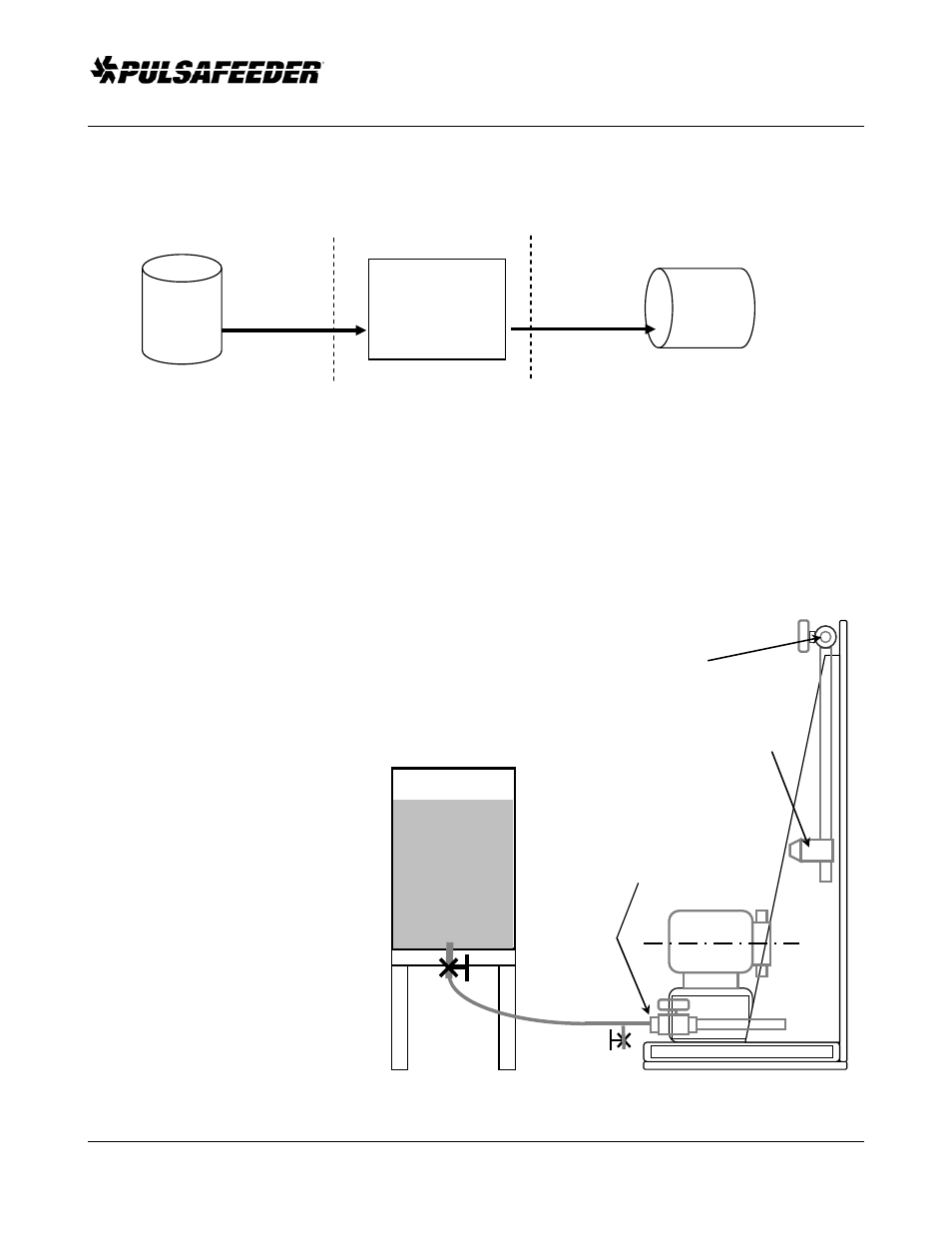
Flooded Suction
Skid Outlet
Connection
Flooded Suction
This is the most trouble free type of
installation. Since the Supply Line tubing is
filled with chemical, priming is
accomplished quickly and the chance of
losing prime is reduced.
Recommended for very low flow rate
applications. e.g. 2 ml/hr, or where
pumping solutions such as sodium
hypochlorite or hydrogen peroxide which
can form air bubbles.
Supply Line should gradually slope
downward from the Solution Tank to the
Skid Suction Connection.
It is strongly recommended to add a drain
provision on the suction side to facilitate
emptying and flushing of the system for
maintenance.
Drain