Initial prime, continued, System with suction lift, Pre-engineered skid systems – Pulsafeeder Pre-Engineered Skid Systems User Manual
Page 14: Installation, operation and maintenance manual, Pump
Pre-Engineered Skid Systems
Installation, Operation and Maintenance Manual
PES00039, Rev. B
Initial Prime
Page 14
Initial Prime, Continued…
System with Suction Lift
With a suction lift configuration, the
entire suction arrangement (suction
line and Skid suction piping) as well
as the pump must be purged of air
before the pump can function. The
pump can evacuate the air, however
this may take considerable time.
Optional:
If the dosing chemical can be
handled safely, it may be helpful to
add dosing chemical to the suction
assembly via the top of the calibration
column. This requires the installation
of a foot valve at the entrance to the
suction line within the chemical
source container. Open the Air Bleed
Valve turning the opening knob
counterclockwise (see Figure 9).
Open Column Isolation Valve. Open
all valves in the Suction Line. Add
dosing chemical into the top of the
Calibration Column until liquid
remains visible. Follow steps, below.
Note that Air Bleed Valve is open.
1. Close Skid Discharge Valve and Column Isolation Valve
2. Open Air Bleed Valve (turn opening knob counterclockwise, see Figure 9)
3. Open all valve(s) on the suction side – Skid Suction Connection Valve and any valve(s) in your
suction line
4. Connect pump/motor to power source (pump/motor off)
5. Start pump using manufacturer’s recommendations for initial operation settings
6. Observe flow through Air Bleed Bypass. When solid stream (no air bubbles) is observed,
pump is primed.
7. Shut off pump.
8. Close Air Bleed Valve (turn opening knob clockwise)
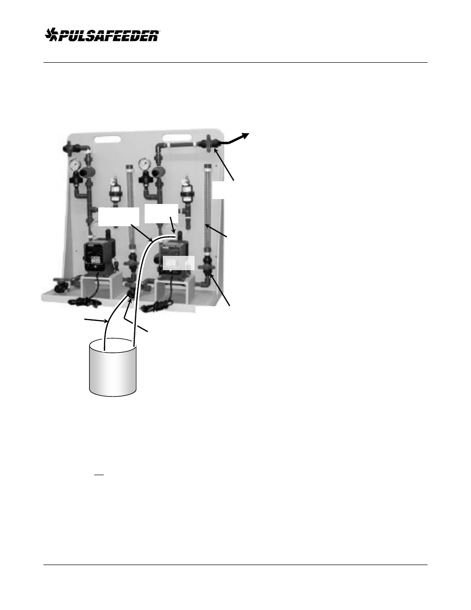
Figure 11
Pump and Suction System Setup for Prime
Suction Lift Configuration
Chemical
Source
Suction Line
Pump
Skid Discharge
Connection/Valve
Column Isolation
Valve
Discharge Line
to Process
Skid Suction
Connection/Valve
Air Bleed
Bypass Line
Air Bleed
Valve
Calibration
Column