Skid layout and components, Pre-engineered skid systems, Installation, operation and maintenance manual – Pulsafeeder Pre-Engineered Skid Systems User Manual
Page 6
Pre-Engineered Skid Systems
Installation, Operation and Maintenance Manual
PES00039, Rev. B
Skid Layout and Components
Page 6
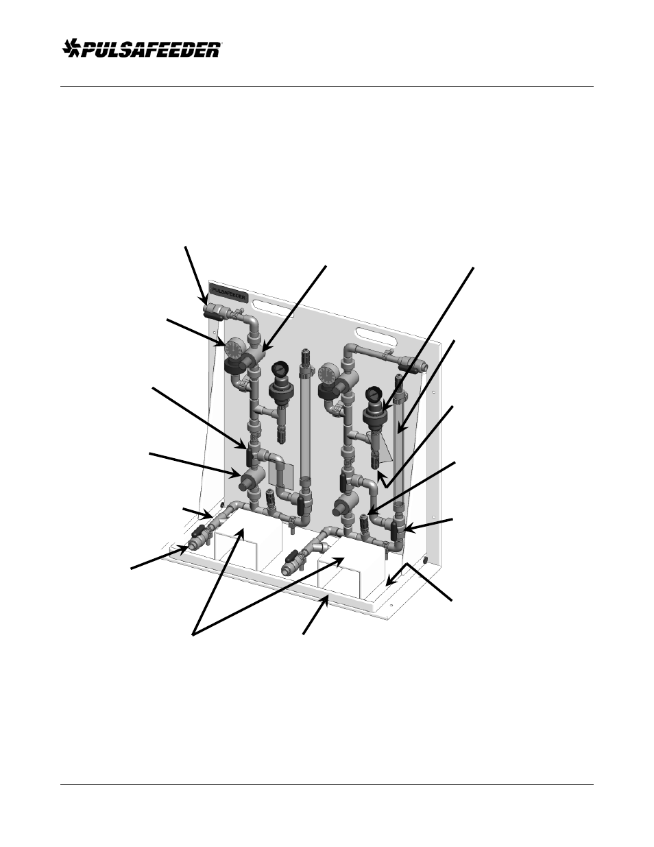
Skid Layout and Components
Figure 2, below, illustrates a dual pump skid system (Pulsafeeder Designation “2A”) for flooded
suction (chemical source above the pump centerline) as shown on Page 7. This system can be used for
two different chemicals or for redundant pump operation with one chemical. Your skid system may be
less complex than this. Note the various components and their descriptions as they apply to your skid
system.
Discharge Isolation Valve
Two-way ball valve to isolate
skid from injection system
Pressure Gauge
Monitors pump discharge
pressure
Pressure Relief Valve
Protects pump and system
piping from over-
pressurization
Column Fill Valve
Three-way ball valve to
enable pump to fill
calibration column
Y-Strainer
Keeps solids from entering
system and damaging pump
or system components
Suction Isolation Valve
Two-way ball valve to
isolate skid from suction
supply
Back Pressure Valve
Provides constant system
discharge pressure and acts
as anti-siphoning valve
Pulsation Dampener
Reduces pulsations from
pump and evens pressure
in injection system
Calibration Column
Enables pump output
flow to be precisely
determined
Pump Discharge Connection
Usually tubing, attachment for
pump discharge to skid piping
Pump Suction Connection
Usually tubing, attachment for
pump suction to skid piping
Column Shut-off/Fill Valve
Three-way valve enables
column to be filled by pump
for calibration and isolates
column for normal operation
Pump Mounting Platform(s)
Provides sturdy support for
pump(s)
Drip Collection Sump
Catches any leakage from pump
or system components
Skid Frame
1/2" high density polyethylene (HDPE)
UV resistant, chemically inert
Figure 2
Skid Layout and Components