7 labeling – nameplate, 8 control input and output connections, 1 motor status input – Pulsafeeder Pulsar ECA NEMA4X User Manual
Page 21: 2 analog input (current loop)
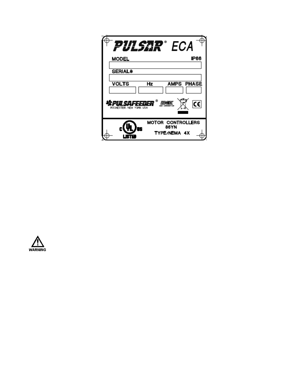
6.7 Labeling – Nameplate
6.8 Control Input and Output Connections
6.8.1
Motor Status Input
The contactor or motor starter controlling the PULSAR motor should be equipped with a
normally open auxiliary contact, which closes to indicate the PULSAR motor is on. This
auxiliary contact, which must be an un-powered, dry contact only, is to be wired to inputs (J4-5
and J4-6) at the ECA, after removing the factory installed jumper wire. Remove approximately
0.3 inches, (7-8mm) of insulation from the end of each conductor. Loosen the terminal strip
screw, and insert the stripped wire end fully into the terminal. Tighten the screw to 5 in-lbs.
(0.5 Nm) to secure the conductor. Make certain that the terminal grips the wire, not the
insulation. It is critical that the ECA receive this input, as stroke length should only be adjusted
when the pump motor is running. An alternate contact that represents motor status (for
example a relay contact in a local control cabinet) can also be used for this function.
D
AMAGE TO THE
ECA
MAY OCCUR IF THE STATUS INPUT WIRING RECOMMENDATIONS ARE NOT
FOLLOWED
.
6.8.2
Analog Input (current loop)
The Analog Input is used for remote control of the pump flow. It accepts current inputs
anywhere in the range of 0 to 25mA (e.g., 4-20mA) provided the “span” (the difference
between the high and low value) is greater than 2mA. Use shielded cable (minimum 2-
conductor) for connection to the Analog Input. Recommended: use shielded cable, 22AWG, 3-
pair, and 6-conductor for connections (e.g. Belden 5545FE). Attach the positive lead to
terminal J4-1 and the negative lead to terminal J4-2 (see Figure 5). Position indicators are
printed on the circuit board below each terminal. Remove approximately 0.3 inches, (7-8mm)
of insulation from the end of each conductor. Loosen the terminal strip screw, and insert the
stripped wire end fully into the terminal. Tighten the screw to 5 in-lbs. (0.5 Nm) to secure the
conductor. Make certain that the terminal grips the wire, not the insulation. The ECA will
provide approximately 160 ohms of resistance to a current loop. It will also accept voltage
signals in the 0-4 volt DC range. The Analog Input is electrically isolated from all other inputs,
outputs and earth ground.
15