Pulsafeeder Pulsar ECA NEMA4X User Manual
Page 18
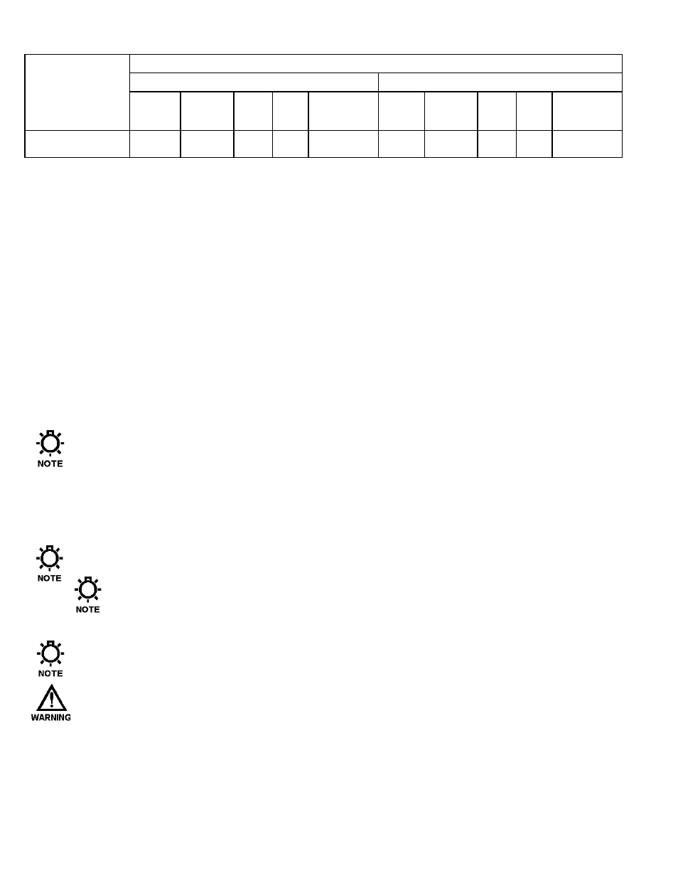
Power
Requirements
Recommended Minimum Wiring and Circuit Breaker
115 VAC Operation
230 VAC Operation
Actual
Circuit
Wire Wire
Safety
Actual
Circuit
Wire Wire
Safety
Draw
Breaker
Size
Size Approvals
1
Draw
Breaker
Size
Size Approvals
1
ECA
200ma
10A
14
AWG
2.5
mm
2
UL, CUL,
CE
200ma
10A
14
AWG
2.5
mm
2
UL, CUL,
CE
Note 1: UL File E217212, Applicable standards are CSA 22.2 14-23, Cenelec EN61326-1,
UL61010-1, and EN61010-1 3
rd
edition
Note the ECA input current ratings from the name plate and check the applicable electrical codes
for required wire type and size, grounding requirements, over-current protection, and incoming
power disconnect before wiring the controller. Connect the proper AC voltage supply to power the
ECA at connector J7. Neutral and Line connection points are indicated on the circuit board under
the connector. The Earth connection is made to the stud on the chassis via a ring terminal
(provided). See Figure 3 for details. Remove approximately 0.3 inches, (7-8mm) of insulation from
the end of each conductor. Loosen the terminal strip screw, and insert the stripped wire end fully
into the terminal. Tighten the screw to 5 in-lbs. (0.5 Nm) to secure the conductor. Make certain
that the terminal grips the wire, not the insulation
.
The operating voltage and frequency of the
ECA is factory configured -- an internal motor and capacitor are sized according to voltage and
frequency. If the power supplied to the unit does not match the factory configuration (shown on
the nameplate), it will malfunction/damage and void the warranty.
Note: Power wiring should have a rating of at least 300 volts AC (rms) and a temperature
rating of at least 105 Degrees C.
A circuit breaker or disconnect switch with fuses, must be provided in accordance with all
applicable local and national electrical codes and regulations. Size external fusing/breaker for
ratings for the wiring used for the unit.
Applicable national and local electrical codes take precedence over recommendations made here.
To ensure proper operation, the ECA should remain powered at all times. A dry
contact input provides the ECA with motor status (on vs. off). See Motor Status Input
Section
Input Power must be run in separate conduit. Do not combine Power and Control wires in
a common conduit!
Field Wiring conductors shall be copper conductors only!
12