Nor-Lake Ice Cream Hardening & Holding Cabinets Models NX362WWW/4 User Manual
Page 11
151555
Rev.
A
07/12
11
PROBE CONNECTIONS
The probes shall be mounted with the bulb upwards to prevent damages due to casual liquid
infiltration. It is recommended to place the thermostat probe away from air streams at return air for
correct measure the average room temperature. Place the defrost termination probe among the
evaporator fins in the coldest place, where most ice is formed, far from heaters or from the warmest
place during defrost, to prevent premature defrost termination.
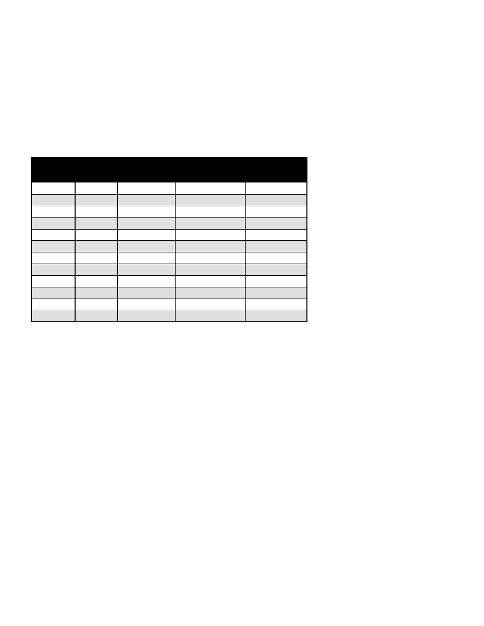
SENSOR PROBE TEMPERATURE AND RESISTANCE
NTC10K Temperature–Resistance
Temp
(ºC)
Temp
(ºF)
R-low
(Kohm)
R-center
(Kohm)
R-high
(Kohm)
-30 -22 109.522 113.347 117.294
-25
-13
84.823
87.559
90.374
-20 -4 66.270 68.237 70.255
-15
5
52.229
53.650
55.104
-10 14 41.477 42.506 43.557
-5
23
33.147
33.892
34.651
0 32
26.678 27.219 27.767
5
41
21.630
22.021
22.417
10 50 17.643 17.926 18.210
15
59
14.472
14.674
14.877
20 68 11.938 12.081 12.224
25
77
9.900
10.000
10.100
SENSOR PROBE
NOTICE: If the probe assembly is disconnected from the main board during normal operation (unit
running), the connectors must be installed in the same position that they had before disconnection (P1
and P2), otherwise the control will not function properly.
The Electronic Refrigeration Control sensors have NTC thermistors. The reference resistance is
30,000 ohms at 77°F (25°C). It carries NTC thermistors with a range of –55°f to 199° F. In case there
is a failure, these sensors should be used in replacement of the sensors shipped with the control. In
order to diagnose faults in the probe, the control has LED functions as a diagnostic tool. When power
is supplied to the control, the LED will turn on and will remain on as long as this condition is satisfied.
When there is a fault in the probe, the LED will blink intermittently. When this occurs, the probe
assembly needs to be replaced. If power is supplied to the control and the LED remains off, there is a
failure in the main relay control and it needs to be replaced.
In case of a probe failure, the control will go into a safety mode of operation. While in safety mode the
control ignores probe inputs and cycles the compressor on for 6 minutes and off for 4 minutes. The
LED will be blinking and signaling that there is something wrong with the probe (E1/E2). To replace
the sensor probes, disconnect power to the control, replace the probes and restart the unit. Since the
wire is fixed to the cabinet, a technician may cut the sensor wire inside the cabinet and splice it with a
new sensor.