Nor-Lake Ice Cream Hardening & Holding Cabinets Models NX362WWW/4 User Manual
Page 10
151555
Rev.
A
07/12
10
MANUAL DEFROST
Defrosting my also be induced manually by keeping the defrost button for 3 seconds. Once defrost
has started, the defrost will go through a defrost and drip time pull down cycle.
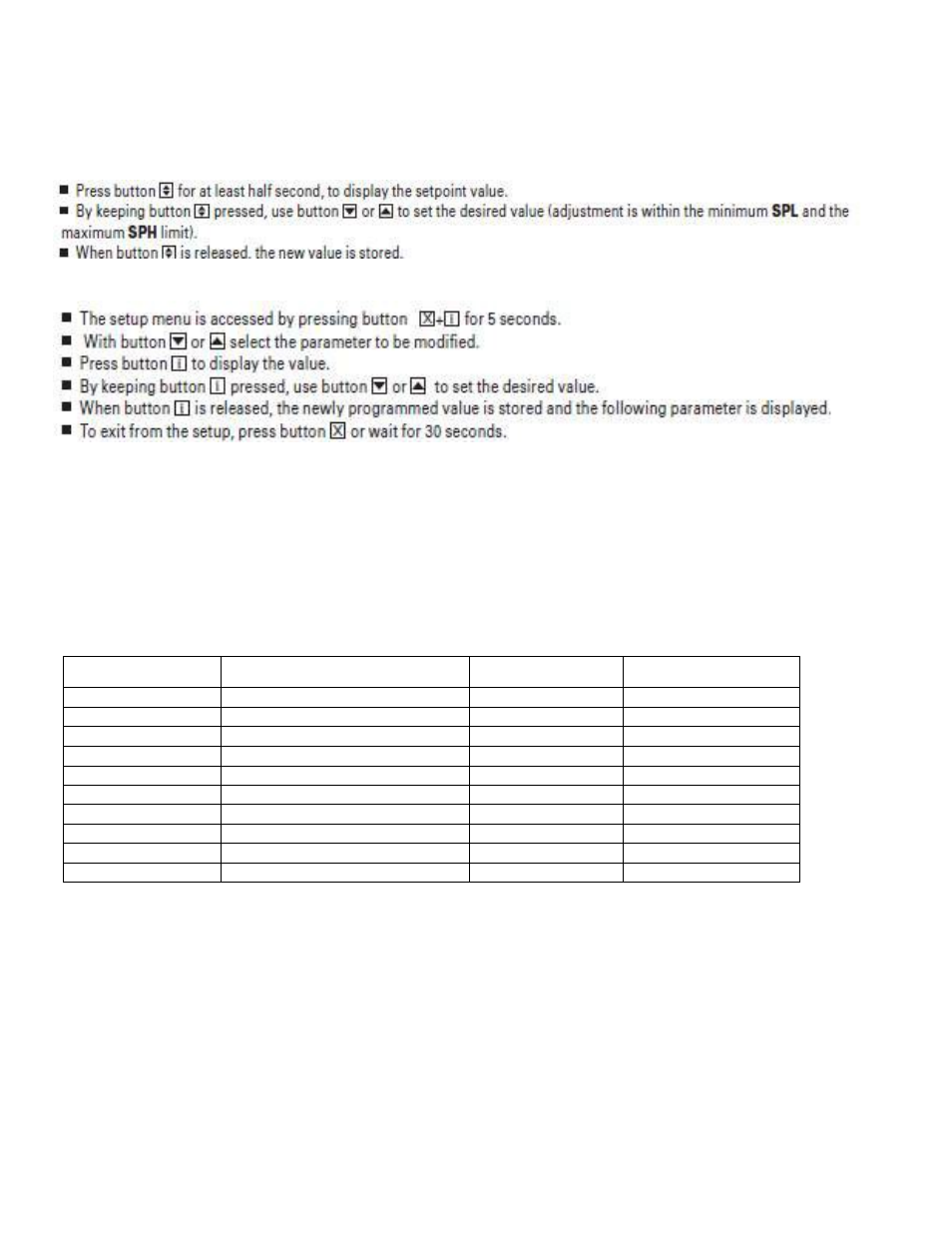
HOW TO CHANGE THE SETPOINT
HOW TO CHANGE A PARAMETER VALUE
NOTE 1: The set value is stored even when the procedure is exited by waiting the time-out to expire.
NOTE 2: The SETPOINT is set at a recommended –20°F at the factory.
NOTE 3: To scroll down the parameters without changing them, press the DOWN button.
LIST OF PARAMETERS
Here is a list of the parameters the value of which can be changed in the programming mode, as well
as their ranges.
Display Symbol
Parameter
Range
Factory Setting
SP Temperature Set Point
SPL.SPH
-20°F
HYS Temperature Differential
1 to 255°F
7°F
SPL Minimum
Temperature limit -35.SPH
-35°F
SPH Maximum
Temperature limit SPH.120°
15°F
AHA High Temperature alarm
-50.120°
35°F
ALA Low
Temperature Alarm
50.120°
-45F
ATD Temperature Alarm Delay
0.120min
30min
DFR
Number of Defrost Cycle per 0.24
4/day
DLI Defrost
Termination
-50.120°
55°F
DTO
Maximum Defrost Duration
1.120min
30min
ELECTRICAL CONNECTIONS
The controller is provided with screw terminal block to connect cables with a cross section up to 2,5
mm2. Before connecting cables make sure the power supply complies with the control’s requirements.
Separate the probe cables from the power supply cables, from the outputs and the power
connections. Do not exceed the maximum current allowed on each relay, in case of heavier loads use
a suitable external relay or contractor’s.