Removing tuner modules, Fig. 12) – AMX DAS-SIRIUS User Manual
Page 11
DAS-SIRIUS Tuner Module
7
DAS-SIRIUS Sirius Satellite Radio Tuner Module
The Controller should only be powered back on once all Tuners are installed and the cover is replaced on the
chassis.
Removing Tuner Modules
In some cases it is necessary to remove the existing Tuner Module, in order to install a different Tuner. Since
each Tuner Module uses 1 source input on the Audio Controller, you may choose to use the source input for
other purposes.
1.
Remove the cover from the Audio Controller.
2.
Carefully remove the ribbon cable from the Tuner Module.
3.
Remove the screws from the Tuner Module cover plate (on the Controller’s rear panel) and carefully slide
the Tuner Module out of the chassis.
4.
To remove TUNER 1, place the TUNER 1 Audio Controller jumpers in the OFF position (FIG. 13).
5.
To remove TUNER 2, place the TUNER 2 Audio Controller jumpers in the OFF position (FIG. 14).
6.
To remove both Tuner Modules, set all Audio Controller jumpers in the OFF position.
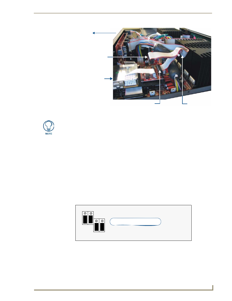
FIG. 12
Tuner 1 / 2 Module Connections (side view of Controller)
rear of Controller
DAS-AMFM
Slot 1 connector
Slot 2 connector
Tuner Ribbon
(side view)
(connect to DAS-SIRIUS
Module)
(shown connected to DAS-AMFM Module)
Cable
While it is recommended that you use the Slot 2 connector on the ribbon cable to
connect the Tuner installed in Slot 2 (in this case, the DAS-AMFM Tuner), the ribbon
cable itself does not determine which Tuner is Tuner 1 and Tuner 2.
This determination is set by the jumper settings on each Tuner Module (see “Tuner 1
Jumper Settings” and “Tuner 2 Jumper Settings” above. Therefore, it is not required
that the connections indicated in FIG. 10 are followed exactly, as long as the Tuner
Jumper Settings are set correctly for each installed Tuner Module.
FIG. 13
Audio Controller Jumper Configuration (No TUNER 1)
Tuner 1 jumpers (in OFF position)
3
1
3
1
TUNER 1
Jumpers
Top Left of Rear-Board Pin Bus