Preparing captive wires, Wiring length guidelines, Wiring a power connection – AMX NetLinx Integrated Controllers NI-3000 User Manual
Page 25
Connections and Wiring
19
NetLinx Integrated Controllers
Preparing captive wires
You will need a wire stripper and flat-blade screwdriver to prepare and connect the captive wires.
1.
Strip 0.25 inch (6.35 mm) of insulation off all wires.
2.
Insert each wire into the appropriate opening on the connector (according to the wiring
diagrams and connector types described in this section).
3.
Tighten the screws to secure the wire in the connector. Do not tighten the screws excessively,
doing so may strip the threads and damage the connector.
Wiring length guidelines
The NetLinx Integrated Controllers require auxiliary 12 VDC power from a PSN to operate
properly. The unit should only have one source of incoming power.
Refer to the following tables for the wiring length information used with the different types of
NetLinx Integrated Controllers:
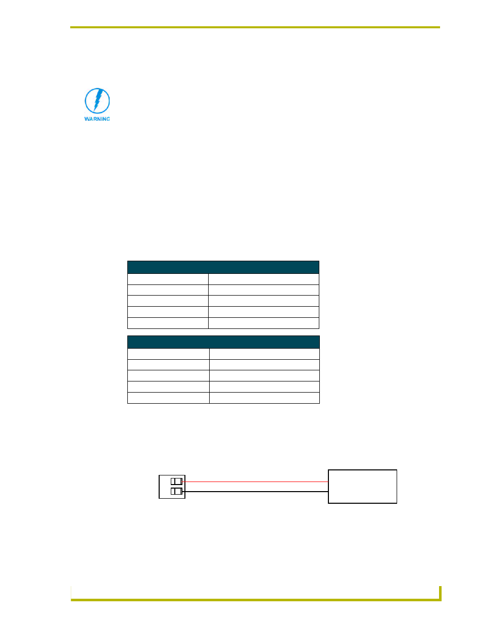
Wiring a power connection
To use the NetLinx 2-pin 3.5 mm mini-Phoenix power supply jack for power transfer from the PSN
power supply, the incoming PWR and GND cables from the PSN must be connected to their
corresponding locations on the 2-pin 3.5 mm mini-Phoenix connector (FIG. 7).
Never pre-tin wires for compression-type connections.
Wiring Guidelines - NI-4000 & NI-3000@ 900 mA
Wire size
Maximum wiring length
18 AWG
130.41 feet (39.75 meters)
20 AWG
82.51 feet (25.15 meters)
22 AWG
51.44 feet (15.68 meters)
24 AWG
32.43 feet (9.88 meters)
Wiring Guidelines - NI-2000 @ 700 mA
Wire size
Maximum wiring length
18 AWG
167.67 feet (51.11 meters)
20 AWG
106.08 feet (32.33 meters)
22 AWG
66.14 feet (20.16 meters)
24 AWG
41.69 feet (12.71 meters)
FIG. 7 2-pin mini-Phoenix connector wiring diagram (direct power)
PWR +
GND -
To the Integrated Controller
NetLinx Power Supply