Rear panel, Connecting the satellite antenna – Ferguson Ariva Link TT User Manual
Page 11
Check whether the subscriber's card has been correctly
inserted into the module. Incorrect insertion of the card may cause
damage to the conditional access module.
Warning: Do not attempt to remove or insert the module
and/or card when the receiver is turned on!!!
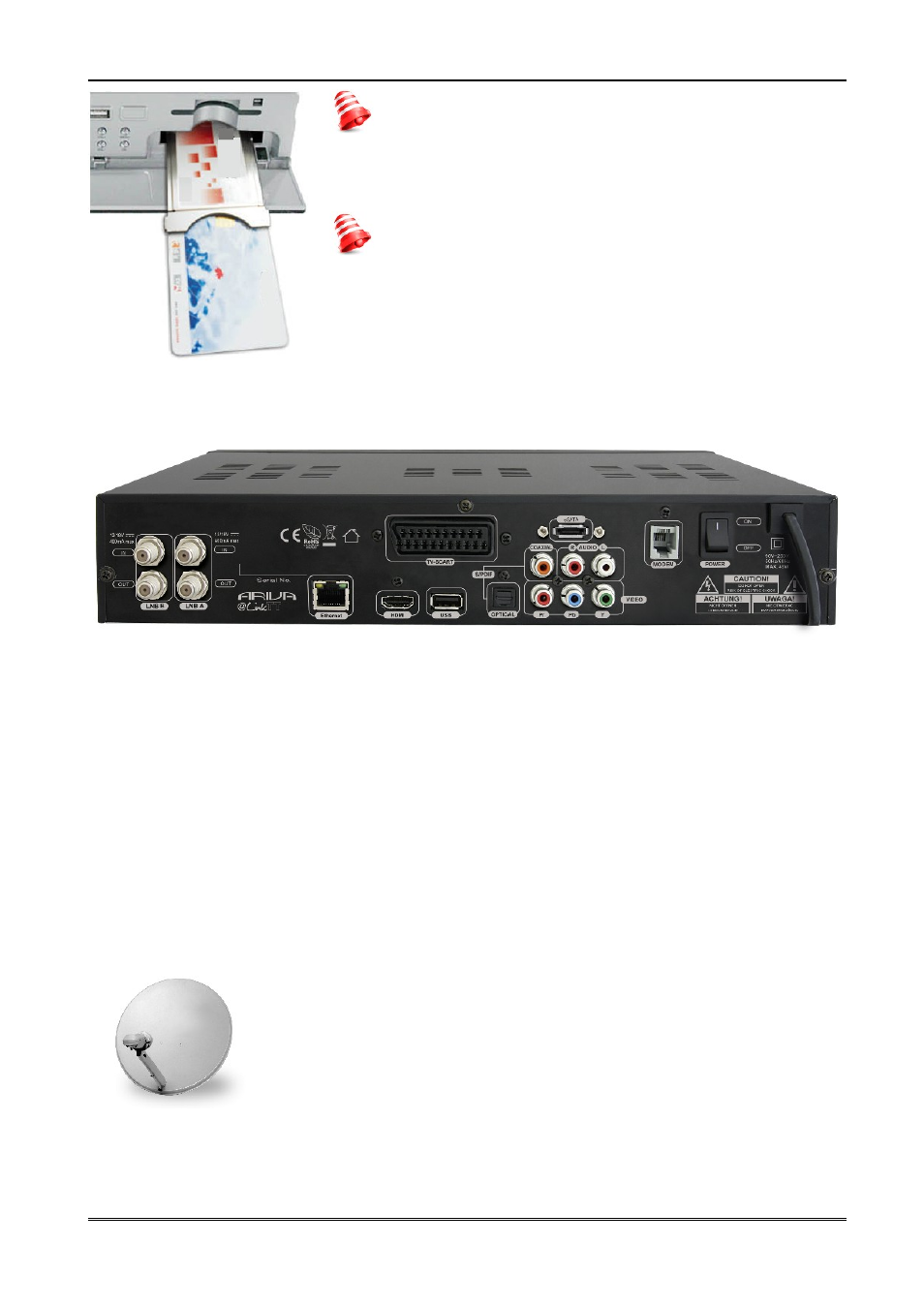
6. Rear panel
LNB IN (A,B):
Inputs of the antenna cable from the converter (LNB).
LOOP OUT (A.,B):
Outputs of the signal from the LNB to another satellite receiver.
ETHERNET:
10/100Mbit RJ-45 Port for home network/Internet.
HDMI:
Digital Video/Audio output for high definition TV's.
USB:
USB 2.0 host connector.
S/PDIF:
Digital optical and coaxial audio output (RCA).
COMPONENT:
Component video output 3 x RCA (YPbPr).
AUDIO (L/R):
Analogue stereo audio output (2 x RCA).
TV SCART:
SCART output to connect to a television.
eSATA:
Connector for an external eSATA Hard disk.
MODEM:
RJ-11 port.
ON/OFF:
Power on/off switch.
7. Connecting the satellite antenna
In order to check the correctness of connection of external equipment, for example a satellite
antenna or converter, read the installation manual or hire a professional technician!
Good reception is conditional on the precise placement of the antenna. Even
the best antenna will cause reception problems if it is incorrectly adjusted.
Even slight placement errors may render reception impossible or
considerably impair image/sound quality. Before installation make sure that
the location is suitable. The proper direction may be initially determined by
making a comparison with other antennas. There should be no objects
directly in front of the antenna, for these may block the signal from
reaching the bowl! Once you select an optimal location for the antenna, fix and adjust it initially,
and then proceed to a precise adjustment. Each antenna is fitted with regulating screws that
make it possible to correct its vertical and horizontal placement.
11