Chapter3, Diagnostics and troubleshooting, Status and activity indicators – Allied Telesis AT-TS90TR User Manual
Page 29: Chapter 3 diagnostics and troubleshooting, Chapter 3, Power fault
19
Chapter 3
Diagnostics and Troubleshooting
Your AT-TS90TR incorporates diagnostic and testing capabilities which
are both convenient to use and cause either minimal or no disruption to
the network. Built-in diagnostic capabilities include system-wide power-
up diagnostics, which are run every time the system is powered or reset.
All tests can be performed locally or remotely using an in-band or out-of-
band Network Management System (NMS).
Status and Activity Indicators
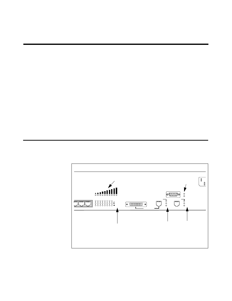
As shown in the following illustration, the front panel includes LEDs that
indicate the status and/or activity of various system components. They are
also described in Table 3 and Table 4.
Figure 9: Front Panel LEDs
100 BASE-TX
NETWORK LOAD
MDI-X)
6
7
8
1
2
3
4
5
6
7
8
RS-232
TERMINAL PORT
LINK
RCV
COL
LINK
RCV
COL
MII
POWER
GREEN - RECEIVE
100 BASE-TX
AMBER - COLLISION
FAULT
PORT A
PORT B
GREEN - LINK
Network Load
Port Activity
-Link
-Receive
-Collision*
100BASE-TX LEDs
-Link
-Receive
-Collision
Status LEDs
Power
Fault
*May be set by management software to indicate transmissions