Front panel, Handle, Power reset button – Allied Telesis AT-TS90TR User Manual
Page 15: 10base-t ports, Port activity leds, Mii port, 100base-tx ports, Rs232c network management port, Status leds, Green - receive
AT-S6 Firmware Module for AT-TS90TR Switch
3
❑
Included is an SNMP agent for configuration and management
using the industry standard Simple Network Management
Protocol (SNMP)
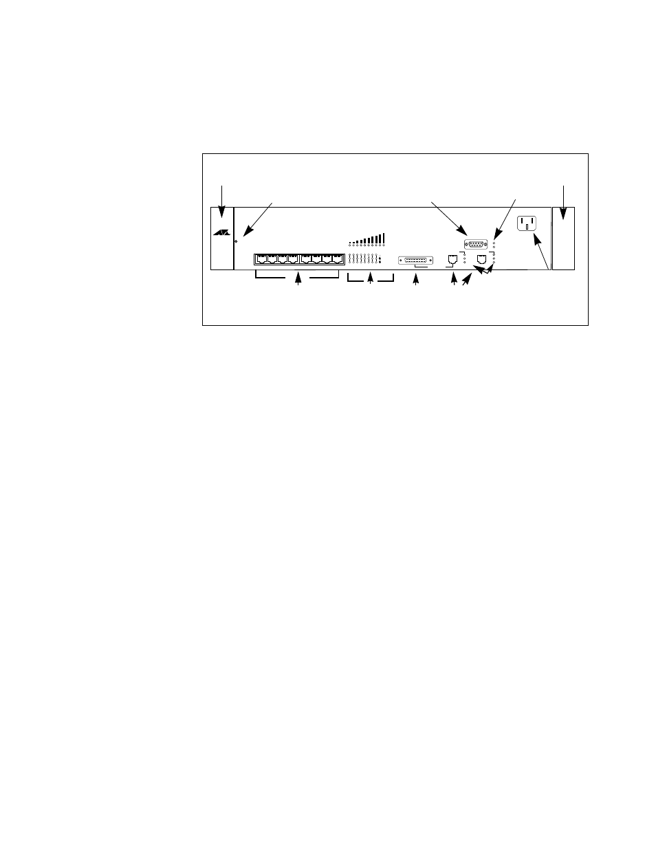
Front Panel
The front panel of an AT-TS90TR, shown in Figure 2, has the following
features and connectors.
Handle.
The handles on each side of the unit cover the mounting brackets
attached to each side of the AT-TS90TR.
Power Reset Button.
The reset Power Reset Button allows you to reboot
the AT-TS90TR from the front panel.
10BASE-T Ports.
There are eight switching 10BASE-T ports available on
the front panel. When the AT-TS90TR is mounted in a
TurboStack chassis,
the left six ports correspond to the six mounting positions in the
TurboStack chassis. The right two ports do not have an internal
connection in a TurboStack installation; they are used only for connection
to external devices.
Port Activity LEDs. The Port Activity LEDs show link, receive, and
collision status for each of the 10BASE-T ports.
MII Port. Media-Independent Interface port connection provides and
alternative connection to the 100BASE-TX port A. The MII port allows a
user to connect a Fast Ethernet transceiver for access to different media,
such as a fiber optic transmission link. The port is autosensing for full or
half duplex operation. When the MII port is being used, the 100BASE-TX
connection to port A should not be used.
100BASE-TX Ports. The two 100 mbps 100BASE-TX ports can be used
for high-speed connections between a high speed source, such as a
backbone or a server, and the AT-TS90TR switch.
RS232C Network Management Port. The RS232C port is a convenient
out-of-band connection to a local workstation for system management.
Status LEDs. The Fault LED lights when the management software
detects an AT-TS90TR malfunction. The Power LED indicates power is
applied to the unit.
Figure 2: AT-TS90TR Front
Panel
RESET
100 BASE-TX
NETWORK LOAD
10BASE-T NETWORK PORTS (MDI-X)
ETHERNET SWITCH
with FAST ETHERNET
1
2
3
4
5
6
7
8
1
2
3
4
5
6
7
8
RS-232
TERMINAL PORT
LINK
RCV
COL
LINK
RCV
COL
MII
POWER
GREEN - RECEIVE
TS90TR
100 BASE-TX
AMBER - COLLISION
TurboStack
FAULT
PORT A
PORT B
GREEN - LINK
RS232C Network
Management Port
10BASE-T Port
Power Reset
10BASE-T Ports
MII Port
Status LEDs
100BASE-TX
Button
AC Power
Handle
Handle
Ports
Activity LEDs
100BASE-TX
Port Activity
LEDs