Powering up the switch, Checking the installation – Allied Telesis AT-8550 User Manual
Page 25
AT-9108, AT-8518, AT-8525, and AT-8550 Installation Guide
2-5
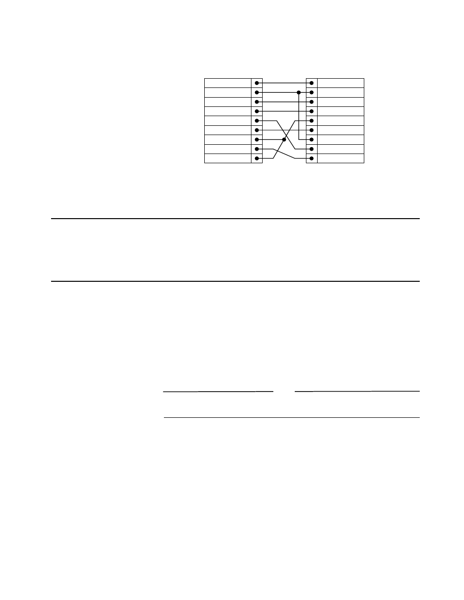
Figure 2-3 shows the pin-outs for a 9-pin to 9-pin PC-AT null-modem serial cable.
Figure 2-3 PC-AT Serial Null Modem Cable Pin-outs
Powering Up the Switch
To turn on power to the switch, connect the power cable to the switch and then to the
wall outlet, and turn the on/off switch to the On position.
Checking the Installation
After turning on power to the switch, it performs a Power On Self-Test (POST).
During the POST, all ports are temporarily disabled, the packet LED is off, the Power
LED is on, and the DIAG LED (AT-9108, AT-8518) or MGMT LED (AT-8525,
AT-8550) flashes.
If the switch passes the POST, the DIAG LED or MGMT LED blinks at a different
rate. If the switch fails the POST, the DIAG LED or MGMT LED shows a solid
yellow light.
Note
For more information on the LED indications, refer to Chapt er1, Tables 1-2, 1-3
and 1-4.
Screen
DTR
TxD
RxD
CTS
Ground
DSR
RTS
DCD
Cable connector: 9-pin female
AT-8525/AT-8550
Cable connector: 9-pin female
PC-AT Serial Port
Screen
DCD
RxD
TxD
DTR
Ground
DSR
RTS
CTS
Shell
4
3
2
8
5
6
7
1
Shell
1
2
3
4
5
6
7
8