Free-standing, Stacking the switch and other devices, Stacking the switch and other device – Allied Telesis AT-8550 User Manual
Page 23: Fit_rack.eps
AT-9108, AT-8518, AT-8525, and AT-8550 Installation Guide
2-3
3.
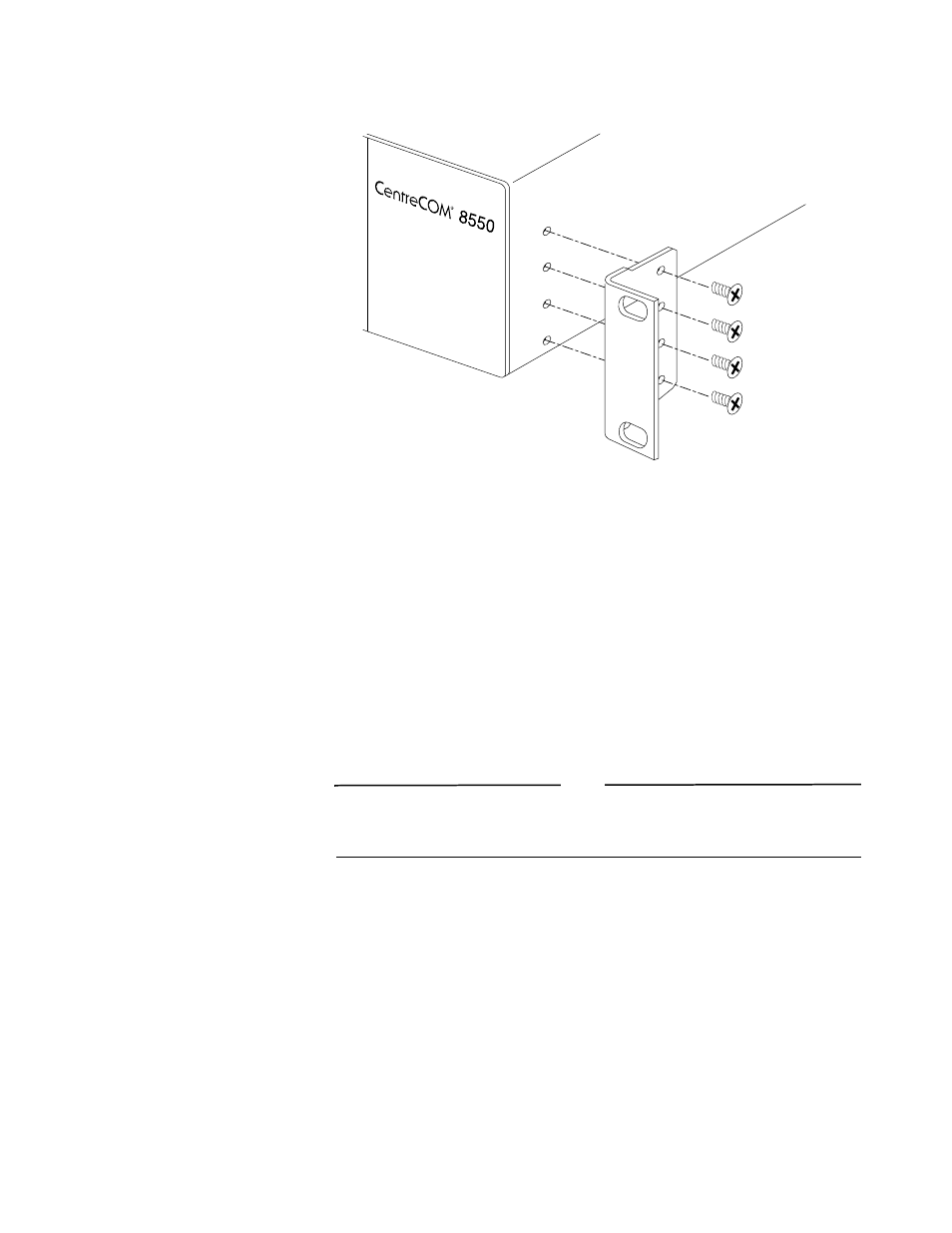
Insert four flathead screws and fully tighten with a suitable screwdriver, as shown
in Figure 2-1.
Figure 2-1 Fitting the Mounting Bracket
4.
Repeat the three previous steps for the other side of the switch.
5.
Insert the switch into the 19-inch rack and secure with suitable screws (not
provided). Ensure that ventilation holes are not obstructed.
6.
Connect the switch to the redundant power supply (if applicable).
7.
Connect cables.
Free-Standing
The switch is supplied with four self-adhesive rubber pads. Apply the pads to the
underside of the device by sticking a pad in the marked area at each corner of the
switch.
Stacking the Switch
and Other Devices
Up to four units can be placed on top of one another.
Note
This section relates only to physically placing the devices on top of one another.
The switch does not form a stack (that is, a number of devices linked together with
special expansion cables to form a single logical device).
Apply the pads to the underside of the device by sticking a pad at each corner of the
switch. Place the devices on top of one another, ensuring that the corners align.
fit_rack.eps