Physical description, Front panel, Rear panel – Allied Telesis FastSwitch8 User Manual
Page 9: Front panel rear panel
FastSwitch8 Installation Guide
3
Physical Description
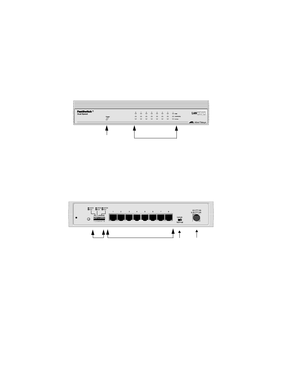
Front Panel
The LanEdge FastSwitch8 front panel consists of Power and Port LED
indicators, as shown in Figure 2.
Figure 2 FastSwitch8 Front Panel defined
Rear Panel
The rear panel of the switch (shown in Figure 3) contains seven 10/100 Mbps
MDI-X (Media Dependent Interface with Crossover) ports and one MDI-X/MDI
port (port 8). Eight dip switches on the rear panel are used to specify the “Link
Mode” for each UTP/STP port. Also on the rear panel are the power adapter
connector and the Normal/Uplink switch for configuring port 8.
Figure 3 Rear Panel View of the FastSwitch8
Port LED Indicators
Power LED
DC Power
10/100M Ports (MDI-X)
Uplink /
Adapter
Normal
Connector
DIP Settings
RESET
1
2
3
4
5
6
7
8
Switch
See also other documents in the category Allied Telesis Computer hardware:
- AT-GS908M (54 pages)
- AT-x230-10GP (80 pages)
- AT-GS950/48PS (64 pages)
- AT-GS950/10PS (386 pages)
- AT-GS950/16PS (386 pages)
- AT-GS950/48PS (386 pages)
- AT-9000 Series (258 pages)
- AT-9000 Series (1480 pages)
- IE200 Series (70 pages)
- AT-GS950/48 (378 pages)
- AT-GS950/48 (60 pages)
- AT-GS950/48 (410 pages)
- AT-GS950/8 (52 pages)
- SwitchBlade x8106 (322 pages)
- SwitchBlade x8112 (322 pages)
- SwitchBlade x8106 (240 pages)
- SwitchBlade x8112 (240 pages)
- AT-TQ Series (172 pages)
- AlliedWare Plus Operating System Version 5.4.4C (x310-26FT,x310-26FP,x310-50FT,x310-50FP) (2220 pages)
- FS970M Series (106 pages)
- 8100S Series (140 pages)
- 8100L Series (116 pages)
- x310 Series (116 pages)
- x310 Series (120 pages)
- AT-GS950/16 (44 pages)
- AT-GS950/24 (404 pages)
- AT-GS950/24 (366 pages)
- AT-GS950/16 (404 pages)
- AT-GS950/16 (364 pages)
- AT-GS950/8 (404 pages)
- AT-GS950/8 (364 pages)
- AT-GS950/8 (52 pages)
- AT-8100 Series (330 pages)
- AT-8100 Series (1962 pages)
- AT-FS970M Series (330 pages)
- AT-FS970M Series (1938 pages)
- SwitchBlade x3106 (288 pages)
- SwitchBlade x3112 (294 pages)
- SwitchBlade x3106 (260 pages)
- SwitchBlade x3112 (222 pages)
- AT-S95 CLI (AT-8000GS Series) (397 pages)
- AT-S94 CLI (AT-8000S Series) (402 pages)
- AT-IMC1000T/SFP (23 pages)
- AT-IMC1000TP/SFP (24 pages)
- AT-SBx3106WMB (44 pages)