Led indicators – Allied Telesis FastSwitch8 User Manual
Page 10
Product Description
4
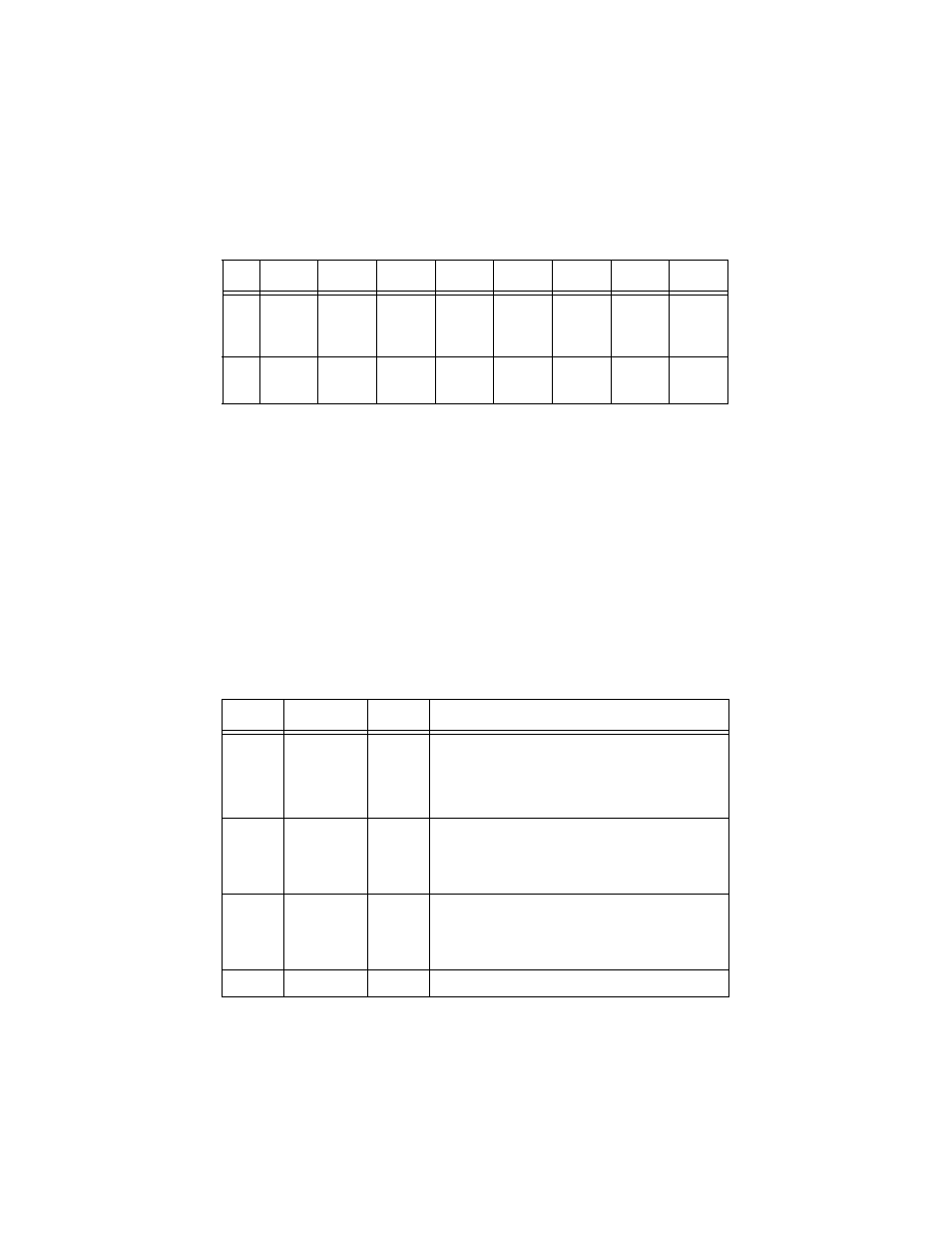
Table 1 lists the dip switch settings.
Table 1 Dip Switch Settings
LED Indicators
The LED indicators are used to monitor and troubleshoot the switch. After the
switch is turned on, the LED indicators should respond as follows:
❑
All of the LED indicators will blink momentarily. This blinking of the
LED indicators represents a reset of the system.
❑
The F.D./Col LED indicator blinks yellow.
❑
The Power LED indicator will remain ON.
Table 2 provides an explanation of each indicator.
Port 1
Port 2
Port 3
Port 4
Port 5
Port 6
Port 7
Port 8
Up
10 Mbps
half-
duplex
10 Mbps
half-
duplex
10 Mbps
full-duplex
100 Mbps
full-duplex
100 Mbps
full-duplex
100 Mbps
full-duplex
100 Mbps
full-duplex
100 Mbps
full-duplex
Down
1
1
Default setting for all ports.
Auto-
negotiate
Auto-
negotiate
Auto-
negotiate
Auto-
negotiate
Auto-
negotiate
Auto-
negotiate
Auto-
negotiate
Auto-
negotiate
Table 2 LED Status
LEDs
Color
State
Description
100 M
Green
ON
OFF
Indicates a 100 Mbps device is connected to a respective
port or the uplink port.
If a 10 Mbps device is connected to a respective port or
the uplink port, the LED indicator is OFF.
Link/
Activity
Green
Green Blinking
ON
OFF
Secure the connection (or Link) to a device at any port.
Reception or transmission (Activity) of data at a port.
No link is established.
F.D./Col
Yellow
Blinking Yellow
ON
OFF
The respective port is in full-duplex mode.
Collisions are occurring on the respective port.
The respective port is in half-duplex mode.
Power
Green
ON
The unit is receiving power.