Led indicators, Figure 4 at-fs704 led indicators, Table 1 led status – Allied Telesis AT-FS704 User Manual
Page 20
Product Description
4
LED Indicators
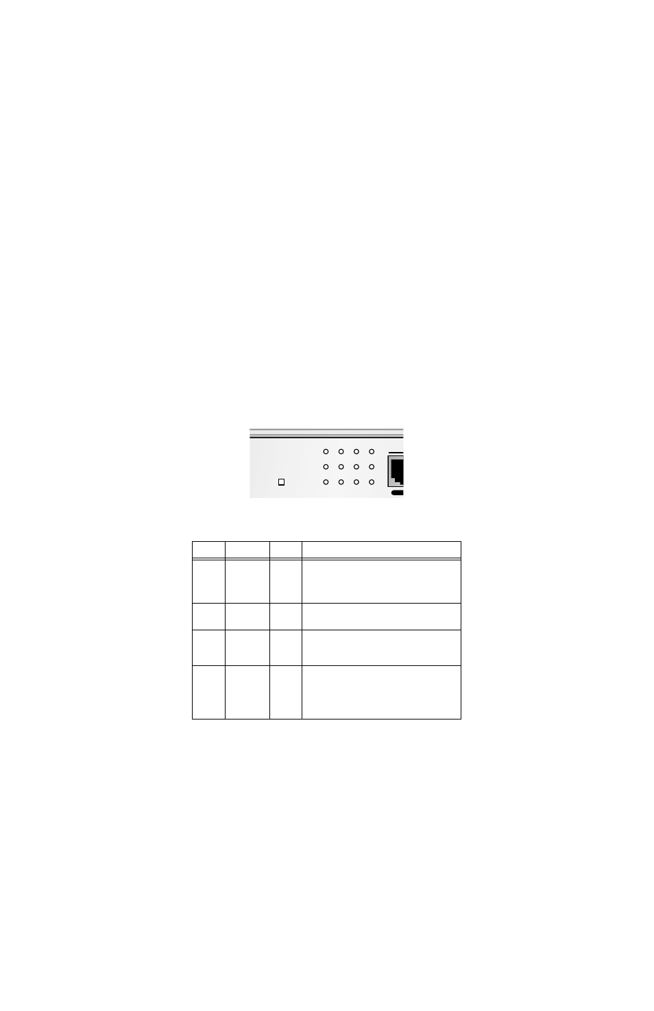
The LED indicators include POWER, 100 M, LINK/ACT (Link/Activity) and
FULL DUP/COLN (Full-duplex/Collision). The LED indicators are used to
facilitate monitoring and troubleshooting of the switch. After the switch is
turned on, the LED indicators should respond as follows:
❑
All of the LED indicators will blink momentarily. This blinking of the
LED indicators represents a reset of the system.
❑
The FDX/Col LED indicators blink from yellow to green.
❑
The power LED indicator will remain ON.
Figure 4 shows the LED indicators on the AT-FS704 and Table 1 provides an
explanation of each indicator:
Figure 4 AT-FS704 LED Indicators
Table 1 LED Status
LEDs
Color
State
Description
100M
Green
ON
OFF
Indicates a 100 Mbps device is connected to a respective
port or the uplink port.
If a 10 Mbps device is connected to a respective port or
the uplink port, the LED indicator is OFF.
LINK/ACT Green
Blinking Green
ON
Secure the connection (or link) to a device at any port.
Reception or transmission (Activity) of data at a port.
FULL DUP
COLN
Green
Blinking Yellow
ON
OFF
Collisions
The respective port is in full-duplex mode.
The respective port is OFF for half-duplex mode.
Collisions are occurring on the respective port.
POWER
Green
ON
OFF
There is power to the switch.
If the POWER LED is not on, check the AC power adapter
to verify that the DC power cord is plugged into a function-
ing wall outlet and that the DC power cord is properly
inserted into the switch’s power connector.
100M
LINK/ACT
FULL DUP
COLN
POWER
1
2
3
4
To