D figure 12, Port – Allied Telesis AT-FS203 User Manual
Page 29
AT-FS200 Series Installation Guide
19
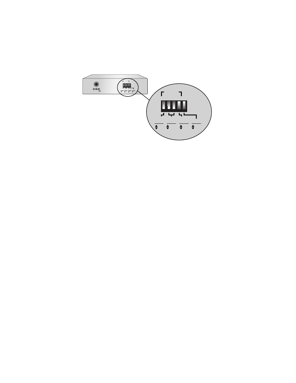
Figure 12 AT-FS201SC and AT-FS202ST DIP Switches
4. If you are installing the switch as a standalone unit, plug the AC/DC
power adapter into an appropriate AC power outlet and insert the power
plug into the DC receptacle, located on the rear panel. If you are installing
the switch in an AT-MCR12 or AT-TRAY4 Chassis, refer to the
appropriate guide for installation instructions.
5.
Verify that the PWR LED on the switch lights green.
6.
For an AT-FS201 or AT-FS202 switch, remove the dust cover from the fiber
optic port.
7. For an AT-FS201 or AT-FS202 switch, plug the fiber optic cable into Port
1. Verify that the near-end node transmitter port (TX) is connected to the
far end node receiver port (RX) and vice versa.
8. Plug the twisted pair cable(s) into the RJ-45 connector(s) (Port 2 for an
AT-FS201 or AT-FS202 switch and Ports 1 and 2 for the AT-FS203
switch).
9. Set the MDI/MDI-X switch as follows:
❑
If you are connecting the twisted pair port to a workstation, set the
MDI/MDI-X switch to the MDI-X position.
❑
If you are connecting the twisted pair port to a hub or to another
switch, set the MDI/MDI-X switch to the MDI position. See Figure 13.
12 V D C
2
1
3
4
5
1
2
2 2
PORT
10
100
HALF
FULL
OFF
ON
DUPLEX
MODE
AUTO
NEG
SPEED
(Mbps)
1522
1518
BYTES
2
1
3
4
5
1
2
2 2
PORT
10
100
HALF
FULL
OFF
ON
DUPLEX
MODE
AUTO
NEG
SPEED
(Mbps)
1522
1518
BYTES