Collapsed backbone – Allied Telesis AT-GS900/8E User Manual
Page 21
AT-GS900/xE Gigabit Ethernet Switch Installation Guide
21
Collapsed
Backbone
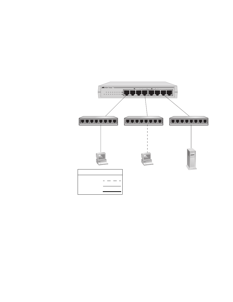
In the topology illustrated in Figure 6, an AT-GS900/8E connects Fast
Ethernet switches that have Gigabit Ethernet uplinks. This type of topology
is often referred to as a collapsed backbone topology. The switch functions
as the focal point of the network and transfers an Ethernet frame between
the Fast Ethernet switches only when the destination end node for the
frame is on a different switch than the end node that originated the frame.
This reduces the amount of unnecessary data traffic in each workgroup,
freeing up bandwidth and improving network performance.
Figure 6. Collapsed Backbone - Hub Topology
AT-GS900/8E
8 Port 10/100/1000 Mbps Ethernet Switch
1
2
3
4
5
6
7
8
1
2
3
4
6
7
8
5
POWER
10/100 LINK
ACT
1000 LINK
ACT
FDX
HDX
COL
1045
5
4
3
2
1
6
7
8
5
4
3
2
1
6
7
8
5
4
3
2
1
6
7
8
Legend
10 Mbps
100 Mbps
1000 Mbps
Fast Ethernet Switches with Gigabit Uplinks
AT-GS900/8E Switch