Network topologies, Power workgroup topology, At-gs900/8e switch – Allied Telesis AT-GS900/8E User Manual
Page 20: Chapter 1: product description 20
Chapter 1: Product Description
20
Network Topologies
This section illustrates two network topologies that you can create with the
AT-GS900/xE switches: a power workgroup and collapsed backbone.
Both types of topologies are described below.
Power
Workgroup
Topology
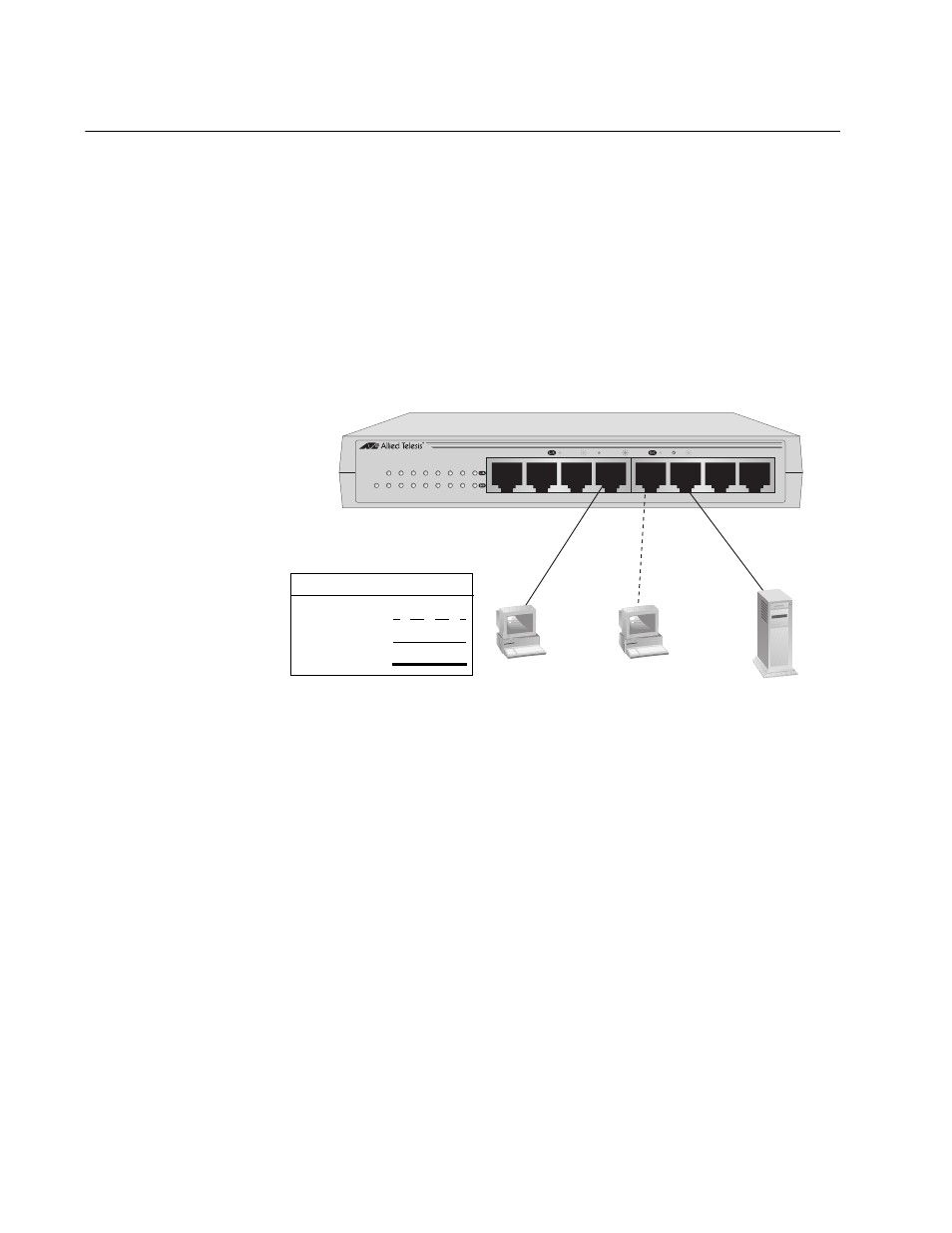
The topology shown in Figure 5 is commonly referred to as a power
workgroup topology. Each workstation or end node is connected directly to
a port on the AT-GS900/8E switch. Each end node has a dedicated data
link to the switch for best performance and reliability. The devices can
operate at 10 Mbps, 100 Mbps or 1000 Mbps.
Figure 5. Power Workgroup Topology
AT-GS900/8E
8 Port 10/100/1000 Mbps Ethernet Switch
1
2
3
4
5
6
7
8
1
2
3
4
6
7
8
5
POWER
10/100 LINK
ACT
1000 LINK
ACT
FDX
HDX
COL
1044
Legend
10 Mbps
100 Mbps
1000 Mbps
AT-GS900/8E Switch