Leds – Allied Telesis AT-GS900/8E User Manual
Page 15
AT-GS900/xE Gigabit Ethernet Switch Installation Guide
15
Type of Cabling
For 10 Mbps operation, Category 3 or better 100 ohm shielded or
unshielded twisted pair cabling is required. For 100 Mbps operation,
Category 5 and Enhanced Category 5 (5E) 100 ohm shielded or
unshielded twisted pair cabling is required.
Maximum Distance
Each twisted pair port has a maximum operating distance of 100 meters
(328 feet).
Auto MDI/MDI-X
All of the twisted pair ports on the switch are auto-MDI and IEEE 802.3ab-
compatible. The ports use the auto-MDI feature to automatically configure
themselves as MDI or MDI-X when connected to an end-node.
Consequently, you can use a straight-through twisted pair cable to
connect any network device to a port.
LEDs
The system and port LEDs on the front panel of the AT-GS900/xE switch
display status information. Each port has three LEDs. Table 1 describes
the system and port LEDs on the AT-GS900/xE Gigabit Ethernet switch.
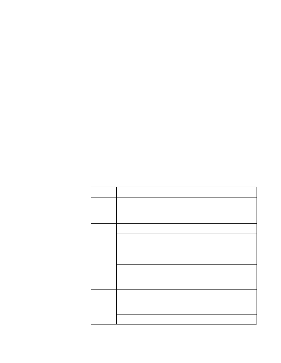
Table 1. System and Port LEDs
LED
State
Description
POWER
Green
The switch is powered ON and operating
normally.
OFF
The switch is not receiving power.
L/A
Green
The port is operating at a speed of 1000 Mbps.
Blinking
Green
The port is receiving activities at 1000 Mbps
speed.
Orange
The port is operating at a speed of 10/100
Mbps.
Blinking
Orange
The port is receiving activities at 10/100 Mbps
speed.
OFF
No link is established on the port.
D/C
Green
The port is operating in full-duplex mode.
Blinking
Green
The port is experiencing a collision in half-
duplex mode.
OFF
The port is operating in half-duplex mode.