Figure 11. rack mounting the switch – Allied Telesis AT-GS900/8 User Manual
Page 38
Chapter 2: Installation
38
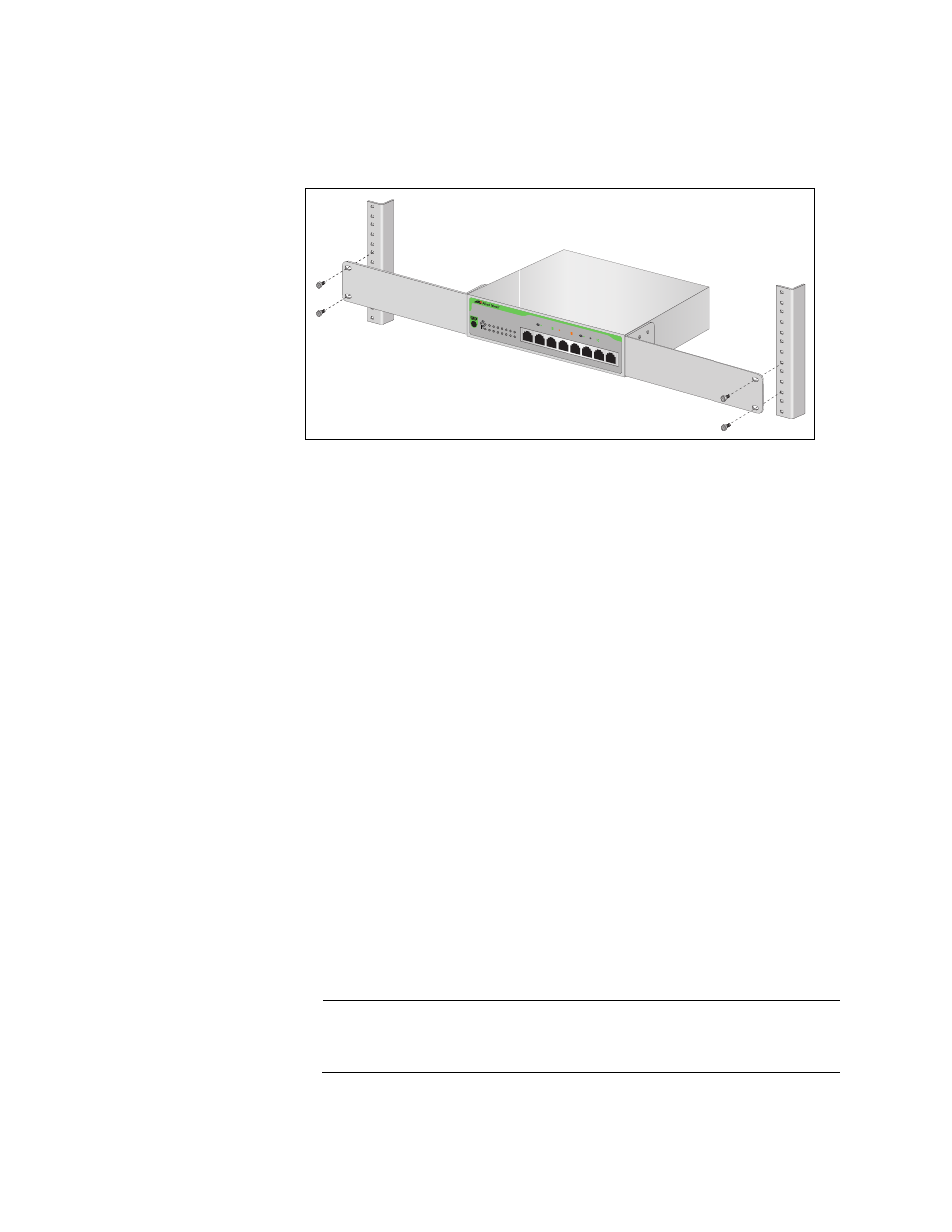
5. Mount the switch in the 19-inch rack using the #10-32 Phillips screws
which are shipped with the product, as illustrated in Figure 11.
Figure 11. Rack Mounting the Switch
6. Connected the twisted pair cables to the twisted pair ports.
When connecting a twisted pair cable to a port, observe the following
guidelines:
An RJ-45 connector should fit snugly into the port on the switch.
The tab on the connector should lock the connector into place.
Check that you are using the appropriate type of twisted pair
cabling. Refer to “Twisted Pair Cabling and Distances” on page 30
for twisted pair cable specifications.
Since the twisted pair port, when operating in Auto-Negotiation, is
Auto MDI/MDI-X, you can use either a straight-through or
crossover twisted pair cable to connect any type of network device
to a port on the switch. If you disable Auto-Negotiation on the port,
the port defaults to MDI-X.
7. Apply AC power to the switch by plugging the power cord into the AC
power connector on the back panel of the unit, as illustrated in
Figure 6 on page 33.
8. Plug the other end or the power cord into a wall outlet.
9. Verify that either the POWER LED is green. If the LED is OFF, refer to
“Troubleshooting” on page 41 for instructions.
Note
The switch perform a self-diagnostic test upon power up. This takes
about 20 seconds to complete.
AT-GS900
/8
8 Port 1
0/100/1
000Base-T
Gigab
it Ether
net Swit
ch
1
2
3
4
5
6
7
8
POWER
10/100 L
INK
ACT
1000 LIN
K
ACT
FDX
HDX
COL
1
2
3
4
6
7
8
5
1919