6 cabling – Allied Telesis AT-IFS802SP/POE User Manual
Page 22
18
AT-IFS802SP/POE(W)-80 User Manual
3.6 Cabling
Use four twisted-pair, Category 5e or above cabling for RJ-45 port connection. The cable between
•
the switch and the link partner (switch, hub, workstation, etc.) must be less than 100 meters (328
ft.) long.
Fiber segment using
•
single-mode connector type must use 9/125 µm single-mode fiber cable.
User can connect two devices in the distance up to
30km.
Fiber segment using
•
multi-mode connector type must use 50 or 62.5/125 µm multi-mode fiber
cable. User can connect two devices up to
2km distances.
Gigabit Copper/SFP (mini-GBIC) combo port:
•
The Industrial switch has the auto-detected Giga port—Gigabit Copper/SFP combo ports. The Gigabit
Copper (10/100/1000T) ports should use Category 5e or above UTP/STP cable for the connection
up to 1000Mbps. The small form-factor pluggable (SFP) is a compact optical transceiver used in optical
communications for both telecommunication and data communications. The SFP slots supporting dual
mode can switch the connection speed between 100 and 1000Mbps. They are used for connecting to
the network segment with single or multi-mode fiber. You can choose the appropriate SFP transceiver
to plug into the slots. Then use proper multi-mode or single-mode fiber according to the transceiver.
With fiber optic, it transmits at speed up to 1000 Mbps and you can prevent noise interference from
the system.
[note]
The SFP/Copper Combo port can’t both work at the same time. The SFP port
has the higher priority than copper port; if you insert the
1000M
SFP transceiver
(which has connected to the remote device via fiber cable) into the SFP port, the
connection of the accompanying copper port will link down.
If you insert the
100M
SFP transceiver into the SFP port even without a fiber
connection to the remote, the connection of the accompanying copper port will
link down immediately.
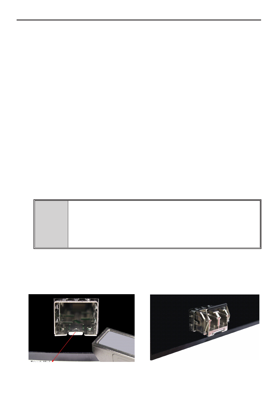
To connect the transceiver and LC cable, please follow the steps shown below:
First, insert the transceiver into the SFP module. Notice that the triangle mark is the bottom of the
module.
Transceiver to the SFP module
Transceiver Inserted