Switchblade x8100 series | system overview, Switchblade x8100 series – chassis – Allied Telesis SwitchBlade x8100 Series User Manual
Page 4
| SwitchBlade x8100 Series System Overview
alliedtelesis
.com
4
SwitchBlade x8100 Series
| System Overview
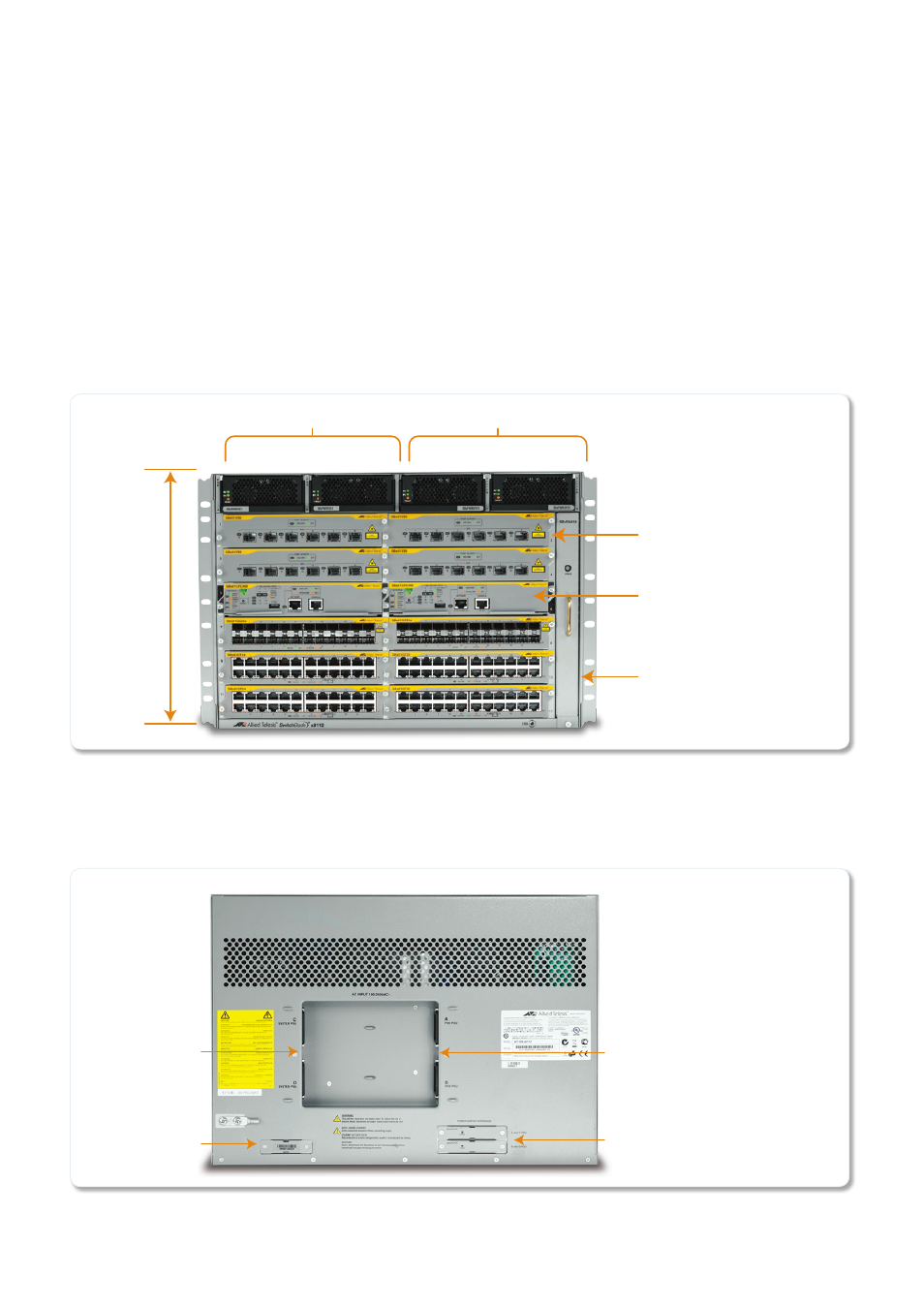
SwitchBlade x8100 Series – Chassis
The SwitchBlade x8112 is a 7 rack unit modular chassis
comprising:
■
2 Controller Fabric Card (CFC) slots
■
10 Line card slots
■
2 System PSU bays
■
2 PoE PSU bays
■
Fan tray
A number of components have specific positions in the chassis:
■
System PSUs use the 2 right hand bays
■
PoE PSUs use the 2 left hand bays
■
CFCs use slots 5 & 6
■
Line cards use slots 1-4, 7-12
PoE PSU bays
System PSU bays
7RU
10 x Line card slots
2 x Control Fabric
card slots
Fan-tray bay
The rear of the chassis provides power cord receptacles for the system and PoE power supplies. The backplane of the SwitchBlade
x8112 is completely passive for high reliability, and is maintenance free. There are 3 extra small covers on the rear of the chassis for
easy access to system components. The left-hand cover provides access to the chassis ID EPROM, and the right-hand covers provide
access to the opto-couplers, used for PSU isolation.
PoE power
cord receptacles
PSU opto-coupler
covers
System power
cord receptacles
Chassis ID
EPROM cover
All of the above system components are hot-swappable to maximise system uptime during maintenance or reconfiguration.