Switchblade x8100 series | system overview, Control card synchronization – Allied Telesis SwitchBlade x8100 Series User Manual
Page 13
SwitchBlade x8100 Series System Overview | 13
SwitchBlade x8100 Series
| System Overview
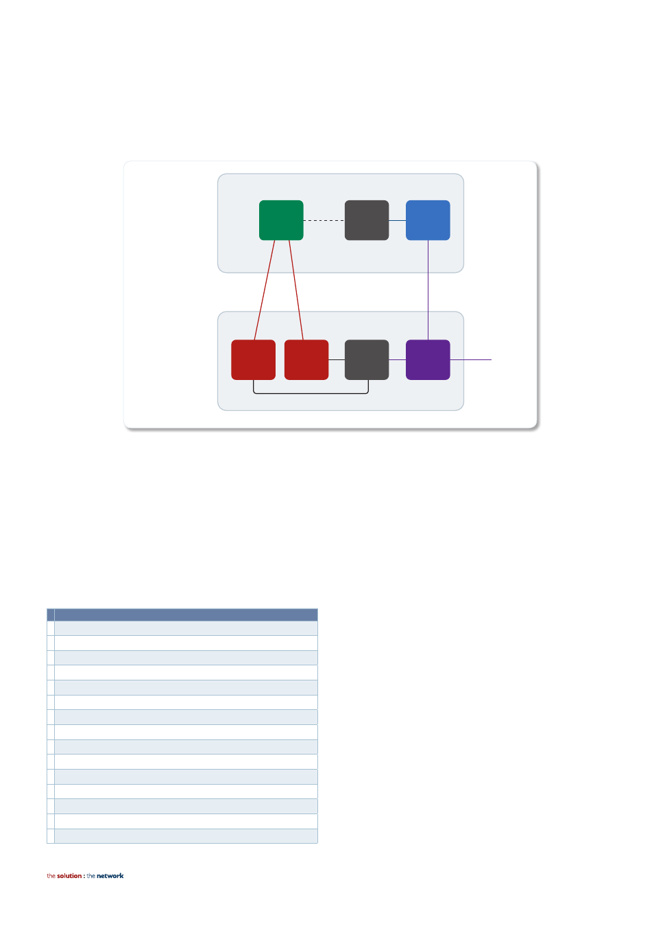
Control plane data is managed by the CPU, as it consists of chassis related communication such as switch management, file transfer
and so on. To facilitate this, the CPU is connected to the control plane switch chip with a 1Gbps link. It is also connected to each
packet processor via 2Gbps PCI Express to manage data traffic that needs to be processed by the switch, for example protocol
management packets (STP, EPSR etc).
Control
Plane
Switch
Chip
Control
Plane
Switch
Chip
1 Gbps link
Control Card
Slot 5
Line Card
Slot 1
1 Gbps links
10 Gbps link
2 Gbps
CPU
Packet
Processor
A
Packet
Processor
B
Packet
Processor
CPU
2 Gbps
1 Gbps links
There is, of course, interconnection with other aspects of the cards not shown, such as SDRAM, Flash memory, USB slot, PHYs etc.
Control card synchronization
When two CFCs are installed in the SwitchBlade x8100, they provide an active/active switching architecture. The packet processors
on both CFCs are fully utilised to double the available backplane bandwidth from 40 to 80Gbps per line-card slot.
One of the CFCs will become the active chassis master. In normal operation this will be the CFC on the left-hand side (slot 5). The
active chassis master manages the system, and processes CPU bound network traffic. The standby CFC runs all network protocol
modules and is kept in sync with the active CFC, so is available in ‘hot-standby’ for near hitless failover if required. The network
information tables that are synchronized between the two CFCs are shown below.
Tables synchronized beTween The Two cFcs
FDB
ARP Table
IP route DB
RIP route DB
OSPF Neighbor/Route DB
VRRP Status
IGMP Snooping
IGMP Multicast group table
PIM-SM/DM multicast route DB
LOCAL RADIUS authentication information
DHCP Server IP address assignment information
EPSR status
802.1x/MAC/WEB authentication information
IPv6 Neighbor table
RiPng route DB
Note: The first three tables listed (FDB, ARP Table and IP route
DB) are also synchronized between the CFC and line cards, so
forwarding/routing information is available locally for lookup on
ingress of external traffic.